Mount for a welding gun for connecting said welding gun to an arm of a welding robot

a welding gun and welding robot technology, applied in the direction of electrode holder supports, arc welding apparatus, soldering auxillary devices, etc., can solve the problems of time-consuming and laborious fixing of corresponding articulated joints, insufficient reliability, and slight displacement of tcp, etc., to achieve simple design, reliable locking off, and simple mounting

Inactive Publication Date: 2015-03-12
DINSE GMBH
View PDF5 Cites 16 Cited by
  • Summary
  • Abstract
  • Description
  • Claims
  • Application Information

AI Technical Summary

Benefits of technology

[0009]The invention is intended for use in this case, and a corresponding simplification of such mounts is to be created. In particular, a mount for welding guns having at least one articulated joint that can be pivoted around an axis of rotation and fixed is to be refined such that this mount is of a simple design and the corresponding articulated joint can be reliably locked-off using simple means, and can likewise be reliably and simply released again for a reshaping of the mount by adjusting to a modified swivel position.

Problems solved by technology

A challenge is posed here, in particular when welding guns are to be replaced, since differently shaped welding guns bring with them a different TCP and the welding guns are frequently not manufactured so precisely, such that, when replacing a welding gun with a new welding gun of essentially the same design, the TCP may be slightly displaced.
In automated welding, however, imprecision in the location of the TCP means a deviation in the position of the weld points that are placed, which can lead to problems and waste during the production.
Herein lies the problem: In the previously envisaged solutions, fixing the corresponding articulated joints is time-consuming and often not sufficiently reliable.
In addition to the complexity associated with making such a replacement, these solutions place a high demand on inventory, due to the need to stock up on the various components of the mounts having a modular design for the different applications, correspondingly costly mounts are also required, in particular different individual modules must be kept in stock, in order to form or, respectively, construct the different retaining geometries.
In so doing however, the inner diameter of the bore and the outer diameter of the sleeve are advantageously coordinated with one another in such a way that these diameters to not allow any substantial amount of play in the movement transverse to the longitudinal axis of the sleeve, and therefore to the axis of rotation of the articulated joint.

Method used


Image

  • Mount for a welding gun for connecting said welding gun to an arm of a welding robot
  • Mount for a welding gun for connecting said welding gun to an arm of a welding robot
  • Mount for a welding gun for connecting said welding gun to an arm of a welding robot

Examples


Embodiment Construction

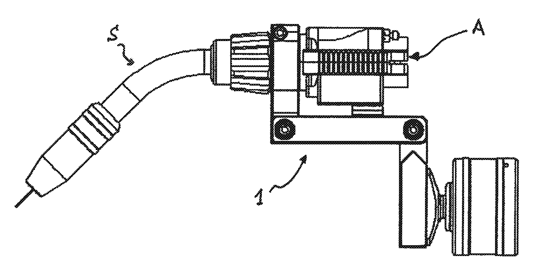
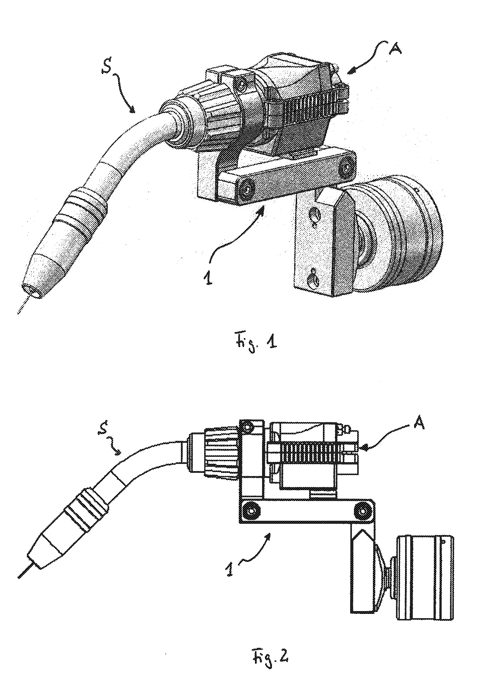
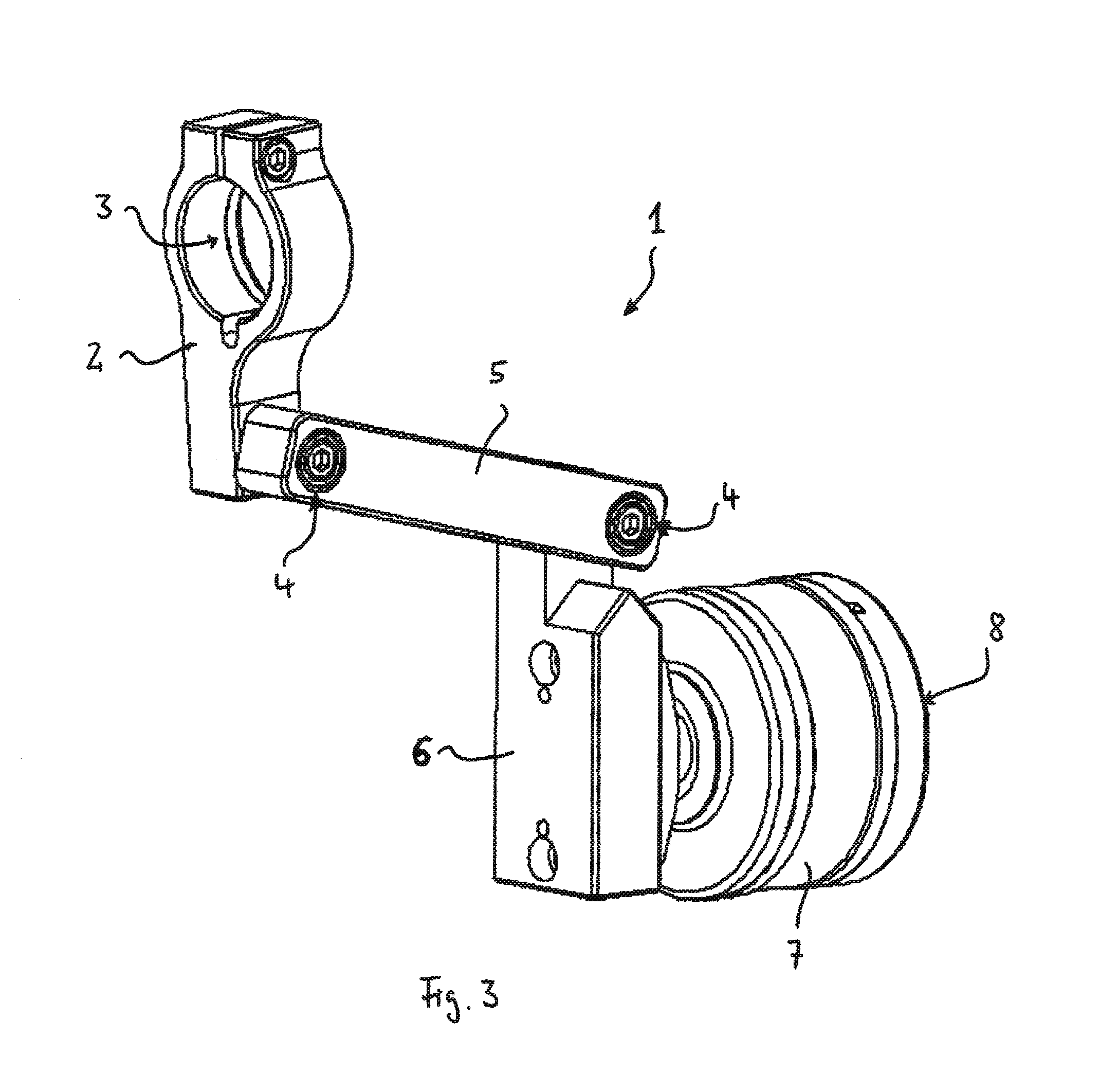
[0040]FIGS. 1 and 2 show two illustrations of a configuration comprising a mount according to the invention in two different views; to begin with, a three-dimensional view in FIG. 1 and a side view in FIG. 2, which are labeled there with the reference numeral 1, and illustrating a welding gun S held in the mount 1. In the case of the welding gun S, it is a welding gun such as those that are used for MIG / MAG welding processes. The welding gun S in this exemplary embodiment is held in an O-shaped retaining ring, which is opened on one side by a slit, which slit is bridged by a bolt for reducing the inner diameter of the retaining ring and for the clamping and clamped fixing of the welding torch S. This type of fastening is well known and need not be explained here in greater detail.

[0041]At a rear end, the welding gun S has a connector A for connection to a so-called cable-hose assembly for the supplying of welding media, thus the welding rod, as well as the welding gas and the weldin...


PUM

PropertyMeasurementUnit
inner diameteraaaaaaaaaa
outer diameteraaaaaaaaaa
circumferenceaaaaaaaaaa

Abstract

A mount for connecting a welding gun to a welding robot's arm. An articulated joint is provided between two rigid elements of the mount. The joint includes a sleeve securable to a first element. A first bore is provided on the second element. The sleeve is inserted into the bore. The bore's inner diameter and the sleeve's outer diameter are such as to allow the second element to turn with the first bore relative to the sleeve. An expansion element provided in the interior of the sleeve is displaceable in the longitudinal direction of the sleeve. The expansion element has a central opening through which a tensioning bolt is passed. The bolt threadably engages a support element causing expansion of the sleeve, thereby causing the sleeve to seize around the circumference thereof in the bore. The expansion and seizing of the sleeve is neutralized by a release and stop.

Description

BACKGROUND OF THE INVENTION[0001]1. Technical Field[0002]The present invention relates to a mount for a welding gun for connecting said welding gun to an arm of a welding robot having the features where the mount has a first connector for forming a connection with the robot arm and a second connector for forming a connection with the welding gun. In addition, it relates to an articulated joint for a mount for a welding gun, said articulated joint being formed between two rigid elements such that it can be pivoted around an axis of rotation and can be locked in a swivel position.[0003]2. Background Information[0004]In modern mass production, automatic welding machines or, respectively, welding robots, in particular such as those used in MIG and MAG welding, are frequently used for joining processes, especially for metal workpieces. Here, multi-axis robots are frequently used, which have robot arms that are suitably designed to move around movement axes, at the ends of which arms, wel...

Claims


Application Information

Patent Timeline
Patent Type & Authority Applications(United States)
IPC IPC(8): B23K9/28
CPCB23K9/287B23K9/173B23K9/295B23K37/0241F16C11/103Y10S901/28Y10S901/42
Inventor LUTGENAU, ALBERT
Owner DINSE GMBH
Why Eureka
Try Eureka