Method for component mounting

a technology for components and mounting devices, which is applied in the direction of manufacturing tools, instruments, transportation and packaging, etc., can solve the problems of difficult to check the surface condition of the nozzle tip after the release of a component, the inability to add a new detection device, such as a sensor, to the apparatus for the purpose of this check, and the inability to meet the requirements of space and cost, so as to avoid any possible negative impact on the operation of the component mounting operation and improve the density of the component mounting

Inactive Publication Date: 2006-06-27
PANASONIC CORP
View PDF11 Cites 17 Cited by
  • Summary
  • Abstract
  • Description
  • Claims
  • Application Information

AI Technical Summary

Benefits of technology

[0033]Still another aspect of the present invention relates to a component mounting apparatus comprising: a supplying device for supplying components to a component supply; a placement head for picking up a component from the component supply, and mounting the component onto a circuit substrate which is positioned and firmly held; a detecting device for detecting a holding condition of the component held by a component holder attached to the component placement head; a collecting box for collecting components if it is determined by the detecting device that these components are held in an improper condition for mounting; and a transferring device for transferring the placement head to at least stations of picking up components, detecting component holding conditions, mounting the components onto the circuit substrate, and collecting components, wherein the component mounting apparatus has a controller which controls production operations so as to perform a checking operation as to whether any debris exists at the component holder of the placement head by use of the detecting device, immediately after production operations are started and before the placement head picks up a first component. This is to avoid any possible negative impact on a component mounting operation, by checking whether any debris remains on the component holder immediately after production operations are started.
[0034]Another aspect of the present invention relates to a component mounting apparatus, wherein the detecting device recognizes a displacement value between the component and the component holder, and determines that the component is held in an improper condition for mounting if the displacement is out of a predetermined allowable range of displacement. This is for improving density of components mounted on a circuit substrate by predetermining an allowable range of the above displacement.
[0035]Another aspect of the present invention relates to a component mounting apparatus further comprising a debris removing device for removing debris from the component holder, which debris removing device cleans the component holder and removes debris from it in case debris is found during the checking or confirming operation, and / or in case the component holder has released the component held in the improper condition for mounting into the collecting box. The above debris removing device comprises any one of an air nozzle to blow compressed air toward the component holder, a vacuum suction nozzle to cause a suction effect in the vicinity of the component holder, a brush like material to clean the component holder, or any combination thereof.
[0036]Yet another aspect of the present invention relates to a component mounting apparatus comprising: a supplying device for supplying components to a component supply; a placement head for picking up a component from the component supply, and mounting the component onto a circuit substrate which is positioned and firmly held; a detecting device for detecting a holding condition of the component held by a component holder attached to the component placement head; a collecting box for collecting components if it is determined by the detecting device that these components are held in improper conditions for mounting; and a transferring device for transferring the placement head to at least stations of picking up components, detecting component holding conditions, mounting the components onto the circuit substrate, and collecting components, wherein the component mounting apparatus has a controller which decelerates a moving speed of the placement head equipped with the component holder until the component holder releases a component, held in an improper condition for mounting, into the collecting box. This is to avoid possible falling of the component from the component holder when it is held in the improper condition.

Problems solved by technology

Because of recent trends of miniaturization of components, as well as increasing of density of mounted components on a single circuit substrate, a tip surface of a sucking nozzle has become smaller, and this makes it more difficult to confirm whether any debris exists on a tip of the nozzle before a component pick up operation is started, or to confirm whether a component is securely released after it is determined that the component is in an improperly held condition.
In the conventional operations, a surface condition of the nozzle tip after the nozzle has released a component may not be checked satisfactorily.
Adding a new detecting device, such as a sensor, to the apparatus for a purpose of this checking is also difficult from view points of space and cost.
If the nozzle fails to release a component, such a remaining component, or debris, may interfere with a new component when the nozzle approaches the new component to pick it up.
This may damage both of the components, or in an extreme case, the nozzle itself as well.
Moreover, if a small portion of a component, or debris, remains at the tip of the nozzle, vacuum power for sucking a component may be lowered, and hence, the component may not be sucked and held in a proper condition, and may cause a problem for mounting operations.
Furthermore, if the nozzle fails to release a component at releasing station 22, and such a component remains at the tip of the nozzle in an unstable condition for the sake of an improper sucking operation, the component may fall on the circuit substrate when the component is transported by the nozzle.
This may cause damage to other components already mounted on the circuit substrate, or may cause damage to other nozzles when they perform mounting operations.
For these other types of mounting, too, it is a problem if a component, held in an improper condition, is not securely released at the releasing station 22.

Method used


Image

  • Method for component mounting
  • Method for component mounting
  • Method for component mounting

Examples


first embodiment

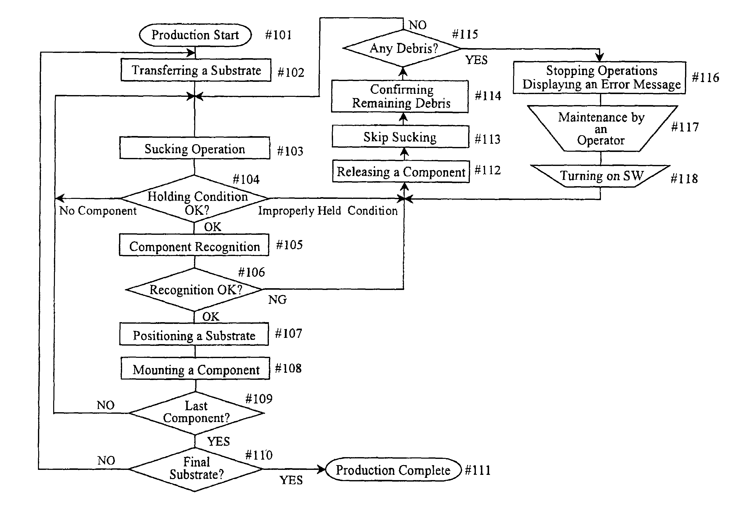
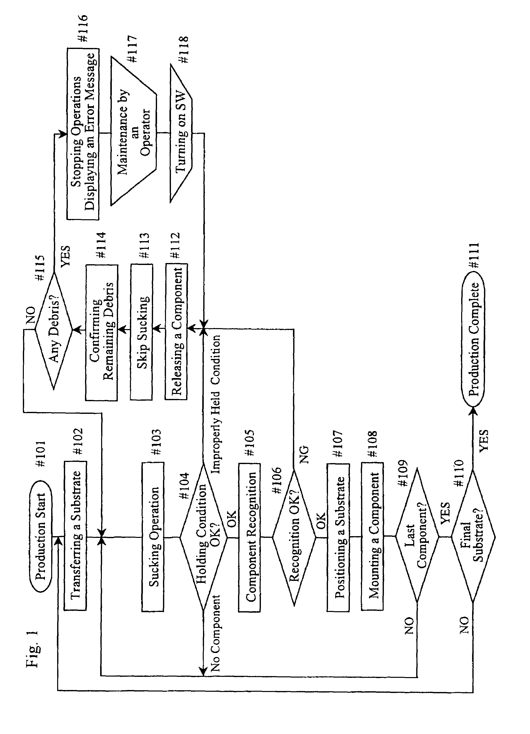
[0053]FIG. 1 shows a flow chart of a method of component mounting according to the present invention. Structures of a main body of a component mounting apparatus performing the method of the present embodiment are similar to those of the prior art described above by referring to FIG. 7. According to the method of the present embodiment, a nozzle which has released a component held in an improper condition is subjected to confirming whether any debris remains and exists at a tip of the nozzle. That particular nozzle is allowed to pick up a new component only if it is confirmed that no debris remains at its tip.

[0054]In the method of component mounting according to the present embodiment shown in FIG. 1, after production operations are started during step #101, a circuit substrate 21 is fed into the apparatus and firmly held by a circuit substrate holder during step #102, and a component 3 is picked up from a component supply 2 during step #103. Then, during step #104, a holding condi...

second embodiment

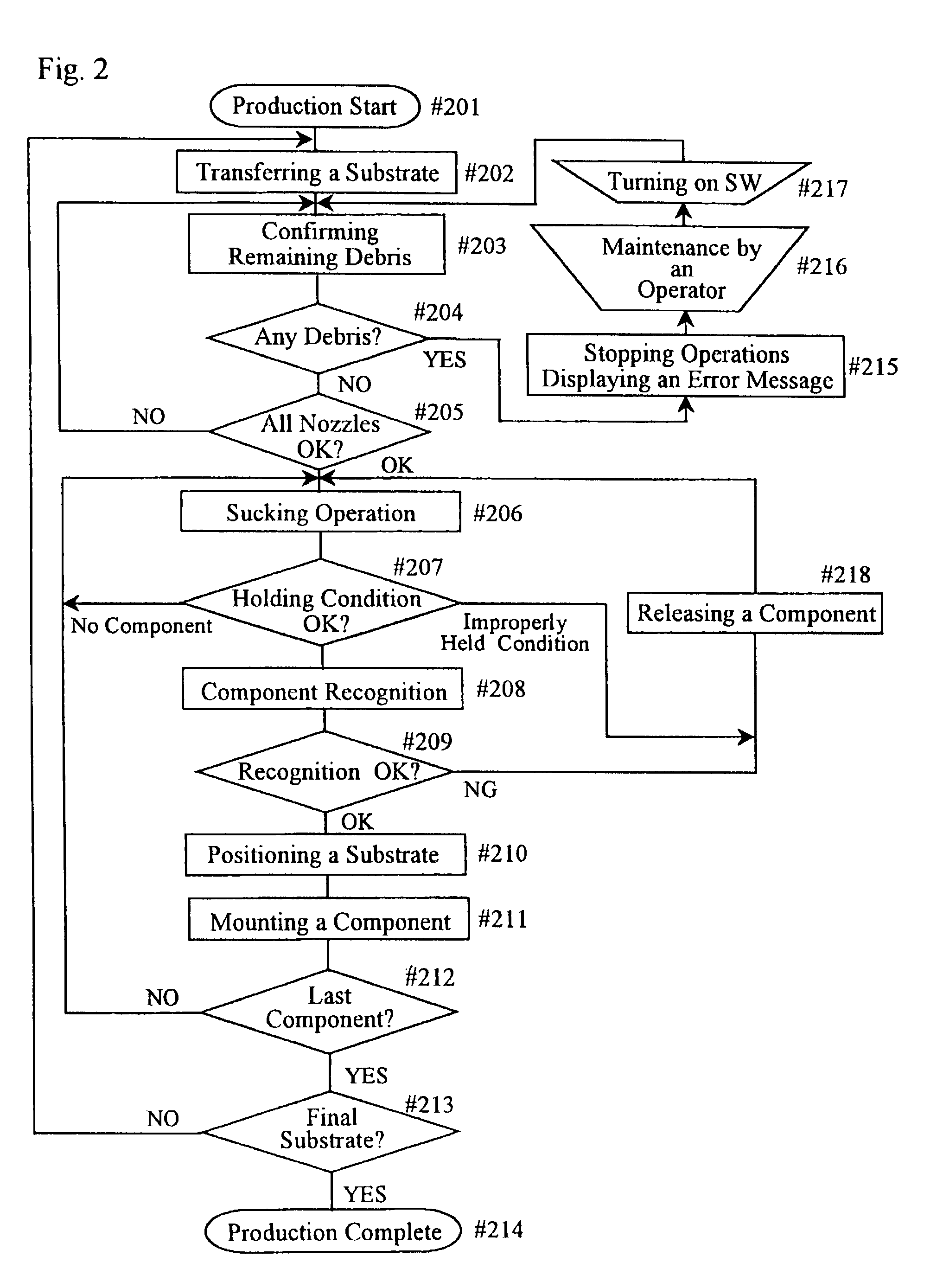
[0060]Next, a method and an apparatus for component mounting according to the present invention will now be described. In the present embodiment, all nozzles are subjected to checking whether any debris exists immediately after production operations are started, and a component pick up operation is started only after this checking procedure is conducted. The term “operation start” here may include any production operation start timing, such as starting a different production lot after production of a specific model has completed, starting production operations after mechanical problems, starting production operations after operators' break time, or starting production operations after operators' shift change. In addition, if it is necessary, detection procedures mentioned above may be performed periodically at a certain time interval during the production operations. The term “immediately after production operations are started” means a timing immediately after starting an operation...

third embodiment

[0068]Next, a method and an apparatus of component mounting according to the present invention are now described by referring to FIG. 3. According to the method of component mounting of the present embodiment, an allowable range of displacement Δa between a sucking point of component 3 and nozzle 14 is predetermined. If this displacement measured is out of such an allowable range, the component 3 is to be released into collecting box 23 at releasing station 22. Further, according to the method of component mounting of the present embodiment, a controller is provided for decelerating a moving speed of the nozzle 14 until the nozzle 14 releases the component 3, in case it is determined that the displacement Δa is out of the predetermined allowable range. Decelerating the moving speed of the nozzle is made for a purpose of avoiding any possible falling of the component 3 held in an improper condition, thereby avoiding possible damage to other components already mounted on a circuit sub...


PUM

PropertyMeasurementUnit
displacementaaaaaaaaaa
densityaaaaaaaaaa
sizeaaaaaaaaaa

Abstract

There are provided a method and apparatus of component mounting capable of avoiding damage caused by production operations with a component holder having debris thereon. If it is determined during a detecting step of a component holding condition that a component is held by a component holder in an improper condition for mounting, the component holder releases such a component into a collecting box, and skips a pick up operation at a next round of a pick up station. The component holder is then subjected to confirming whether any debris exists by using, preferably, a condition sensor, and the component holder picks up a new component if it is confirmed that no debris exists. If debris is found during the confirming step, production operations are stopped, or a warning is generated. After maintenance of the component holder is completed, production operations are restarted.

Description

[0001]This application is a National Stage Application of PCT / JP00 / 08639, filed Dec. 7, 2000.BACKGROUND OF THE INVENTION[0002]The present invention relates to a method for mounting components, such as electronic components, onto a circuit substrate, such as an electronic circuit board, as well as an apparatus for mounting components which is capable of performing such a method. The present invention also relates to a computer readable storage medium for performing such a method.[0003]In the field of component mounting for mounting components, such as electronic components, onto a circuit substrate, such as an electronic circuit board, a plurality of supplying devices carrying numbers of components are attached to a component mounting apparatus, and the components are picked up one after another from these supplying devices in a predetermined order. Each component is then detected as to whether it is held by a component holder in a proper condition for mounting. If it is determined t...

Claims


Application Information

Patent Timeline
Patent Type & Authority Patents(United States)
IPC IPC(8): B23P19/00G06Q50/00G06Q50/04H05K13/04H05K13/08
CPCH05K13/0413H05K13/08Y10T29/53174Y10T29/49128Y10T29/49133Y10T29/53191Y10T29/49Y10T29/53052Y10T29/53091H05K13/0813
Inventor YAMAMOTO, HIROKIIMAFUKU, SHIGEKIIZUMIDA, KEIZOKURIBAYASHI, TAKESHI
Owner PANASONIC CORP
Why Eureka
Try Eureka