
Locking device for multistage actuating cylinder

A technology of locking device and actuating cylinder, which is applied to the chassis and other directions, can solve the problems that the retractable mechanism of the landing outriggers cannot be reused, cannot meet the high load capacity of the outriggers, and does not have a multi-stage deployment stroke, etc., to achieve processing Simple, long service life, long deployment stroke effect

Active Publication Date: 2017-01-04
NANJING UNIV OF AERONAUTICS & ASTRONAUTICS
View PDF7 Cites 7 Cited by
  • Summary
  • Abstract
  • Description
  • Claims
  • Application Information

AI Technical Summary

Problems solved by technology

[0003] The traditional carrier landing outrigger retractable mechanism usually has a complex structure, which mainly releases the initial locking state through pyrotechnics, and then uses the torsion spring on the hinge of the unfolding bracket to realize the deployment. It can be seen that the traditional landing outrigger retractable Institutions are not reusable
Moreover, the traditional multi-stage retractable actuator usually does not have the function of automatic locking and unlocking, and cannot meet the requirements of high load-carrying capacity of the landing outriggers.
At the same time, for the traditional retractable actuator, it does not have the advantage of long deployment stroke brought by multi-stage deployment.

Method used


Image

  • Locking device for multistage actuating cylinder
  • Locking device for multistage actuating cylinder
  • Locking device for multistage actuating cylinder

Examples


Embodiment Construction

[0022] The present invention will be further described below in conjunction with accompanying drawing.

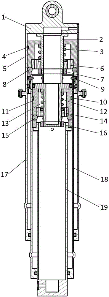
[0023] The invention provides a multi-stage actuator locking device, the overall structure of the device is as follows: figure 1 As shown, the expanded structure of the inner cylinder is shown as figure 2 As shown, the fully expanded structure is shown as image 3 As shown, it includes an end cap 1, an outer cylinder 17, an intermediate cylinder 18, an inner cylinder 19, an upper sliding sleeve 5, a lower sliding sleeve 11, an upper unlocking sleeve 2, a lower unlocking sleeve 13, an upper locking snap ring 6, Lower locking snap ring 14, upper limit snap ring 7, lower limit snap ring 16, connecting screw 9, upper elastic element 3, lower elastic element 12, upper steel ball 8, lower steel ball 15.

[0024] upper sliding sleeve 5 as Figure 4 As shown, it is installed in the cylinder wall composed of the end cover 1 and the outer cylinder 17. A guide belt 4 and a dynamic...


PUM


Abstract

The invention provides a locking device for a multistage actuating cylinder. The locking device comprises an end cover, an outer barrel, a middle barrel, an inner barrel, upper and lower sliding sleeves, upper and lower unlocking sleeves, upper and lower locking clamp rings, upper and lower limiting clamp rings, connecting screws, upper and lower elastic elements as well as upper and lower steel balls. A highly bearing steel ball locking mechanism is combined with the multistage actuating cylinder, so that the mechanism has high bearing capacity in a locked state, guarantees long unfolding travel of the actuating cylinder, realizes a reusable function on the basis of reliable locking and unlocking, and is applicable to landing support legs of reusable launch vehicles; meanwhile, the mechanism is simple to machine, convenient to mount, capable of realizing automatic collection and release and long in service life.

Description

technical field [0001] The present invention relates to a multi-stage jack locking device for reusable vehicle landing legs. Background technique [0002] With the successful launch and recovery of the reusable vehicle, the landing outriggers of the reusable vehicle are applied. In order to reduce the additional aerodynamic resistance caused by the landing outriggers installed on the surface of the vehicle, usually the landing outriggers need to shrink to In the shell, when the vehicle is about to land, the landing legs are opened by means of pneumatic / hydraulic transmission. At the same time, since the carrier will generate a large impact load on the landing legs during the landing process, in order to ensure that the landing legs can reliably support the carrier under load and prevent the carrier from tipping over, it must be fully extended when the landing legs are fully extended. After the landing, it is locked reliably by the locking device. After the landing and recov...

Claims


Application Information

Patent Timeline
IPC IPC(8): B64C25/26
CPCB64C25/26
Inventor 张明岳帅聂宏肖杰陶海峰夏昊天
Owner NANJING UNIV OF AERONAUTICS & ASTRONAUTICS
Learn More