
Double-arm clamping claw bracket

A claw cow and double-arm technology, applied in the field of double-arm claw corbels, can solve the problems of small space, small variety, high utilization rate of warehouse space, etc., and achieve the effect of meeting storage requirements, strong carrying capacity and improving stability

Inactive Publication Date: 2016-08-31
苏州华驰机械有限公司
View PDF7 Cites 4 Cited by
  • Summary
  • Abstract
  • Description
  • Claims
  • Application Information

AI Technical Summary

Problems solved by technology

[0002] The drive-in rack can provide the largest storage capacity in the smallest space, and is widely used in operations with large storage capacity, small varieties, and frequent in and out of the warehouse; the structure principle of the drive-in rack is to connect several rows of columns and support it with the top beam , connected by corbels and pallet guide rails, pallet goods are racked on the pallet guide rails, forklifts can directly drive into the cargo lane to store and retrieve goods, and the warehouse space utilization rate is high; there is a need between the column pieces and the corbel beams of the drive-in shelves Connected by corbel connectors, single-arm corbels are used on the side, and double-arm corbels are used in the middle, but the existing corbel structure has poor bearing capacity and cannot meet the storage requirements of drive-in shelves

Method used


Image

  • Double-arm clamping claw bracket

Examples


Embodiment Construction

[0011] The present invention is described below in conjunction with accompanying drawing.

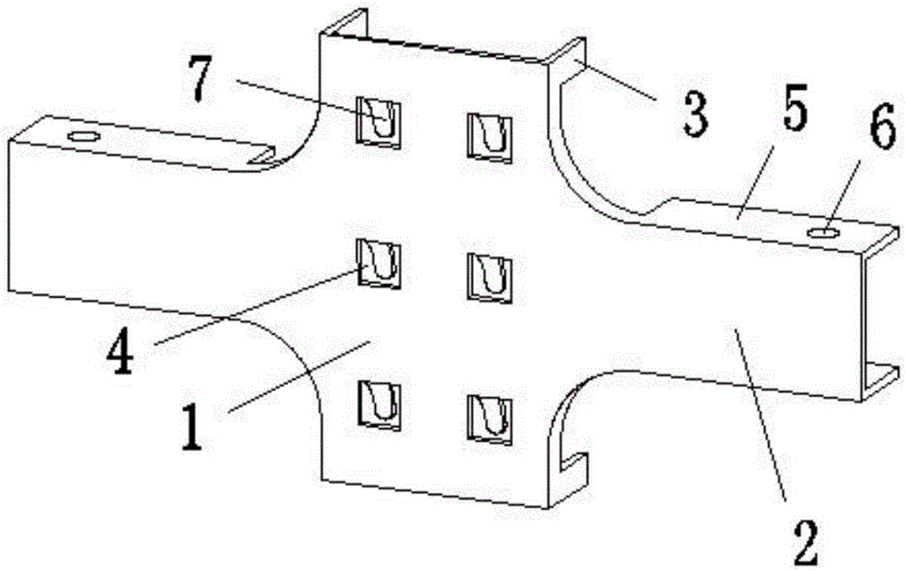
[0012] as attached figure 1 As shown, a double-arm claw bracket according to the present invention includes a vertically arranged column connecting plate 1 and two horizontally arranged beam connecting plates 2, and the two beam connecting plates 2 are respectively arranged on the column connecting plate 1 The left and right sides of the column connecting plate 1 and the two beam connecting plates 2 are located on the same vertical plane, and the column connecting plate 1 and the beam connecting plate 2 are connected by arc surfaces; the four corners of the column connecting plate 1 are all provided with There are column clamping arms 3, and a plurality of symmetrical column connecting grooves 4 are arranged on the column connecting plate 1, and column claws 7 are arranged on each column connecting groove 4; the upper and lower ends of the beam connecting plate 2 are provided with Ther...


PUM


Abstract

The invention discloses a double-arm clamping claw bracket which comprises a vertically-arranged stand column connecting plate and two transversely-arranged cross beam connecting plates. The two cross beam connecting plates are arranged on the left side and the right side of the stand column connecting plate. Stand column clamping arms are arranged at the four corners of the stand column connecting plate. The stand column connecting plate is further provided with multiple symmetric stand column connecting grooves. Each stand column connecting groove is provided with a stand column clamping claw. Cross beam clamping plates are arranged at the upper end and the lower end of each cross beam connecting plate. A cross beam connecting hole is formed in each cross beam clamping plate. The stand column clamping arms, the cross beam clamping plates and the stand column clamping claws are located on the back side of the whole. By means of the double-arm clamping claw bracket, due to the fact that the stand column clamping arms are matched with stand column pieces and are assembled through the stand column clamping claws, and meanwhile the cross beam connecting plates are connected with a bracket beam through the cross beam clamping plates and the cross beam connecting holes, the connecting stability between the stand column piece at the middle portion of a goods shelf and the bracket beam is improved, the bearing capability is high, loading and unloading are convenient, and the storage requirement of the drive-in goods shelf is met.

Description

technical field [0001] The invention relates to a double-arm claw corbel, in particular to a double-arm claw corbel for a drive-in shelf. Background technique [0002] The drive-in rack can provide the largest storage capacity in the smallest space, and is widely used in operations with large storage capacity, small varieties, and frequent in and out of the warehouse; the structure principle of the drive-in rack is to connect several rows of columns and support it with the top beam , connected by corbels and pallet guide rails, pallet goods are racked on the pallet guide rails, forklifts can directly drive into the cargo lane to store and retrieve goods, and the warehouse space utilization rate is high; there is a need between the column pieces and the corbel beams of the drive-in shelves The corbels are connected by connecting parts. The one on the side adopts a single-arm corbel, and the middle uses a double-arm corbel. However, the existing corbel structure has poor beari...

Claims


Application Information

Patent Timeline
IPC IPC(8): B65G1/02
CPCB65G1/02
Inventor 张阿兴
Owner 苏州华驰机械有限公司
Learn More