Image Forming Apparatus

a technology of image forming and forming drums, which is applied in the direction of electrographic process apparatus, instruments, corona discharge, etc., can solve the problems of lowering the image quality, disadvantageous positioning of photoconductor drums relative to the other components of the main body of the apparatus, etc., and achieves high image quality and without reducing the ease of installation or removal

Active Publication Date: 2009-07-02
BROTHER KOGYO KK
View PDF8 Cites 11 Cited by
  • Summary
  • Abstract
  • Description
  • Claims
  • Application Information

AI Technical Summary

Benefits of technology

[0011]According to the specific embodiments of the present invention as will be described below, the plurality of photoconductors can be positioned accurately relative to the other components of the main body of the apparatus without diminishing the ease of operation of installation or removal of the support frame. Consequently, high image quality can be maintained without fail.

Problems solved by technology

In this configuration where the support frame is pulled out straight in a horizontal direction, the support frame would possibly be shifted horizontally in position within the apparatus through an operation of the support frame pulled out from and pushed into the casing of the apparatus, whereby the photoconductor drums could disadvantageously be positioned inaccurately relative to the other components of the main body of the apparatus.
The resulting inaccurate positioning of the photoconductor drums in the apparatus would cause unnecessarily greater forces to act on both of the photoconductor drums and the intermediate transfer belt at their contact surfaces, or make a gap therebetween, which would undesirably produce a problem transferring an image, resultantly lowering the quality of the image.

Method used


Image

  • Image Forming Apparatus
  • Image Forming Apparatus
  • Image Forming Apparatus

Examples


Embodiment Construction

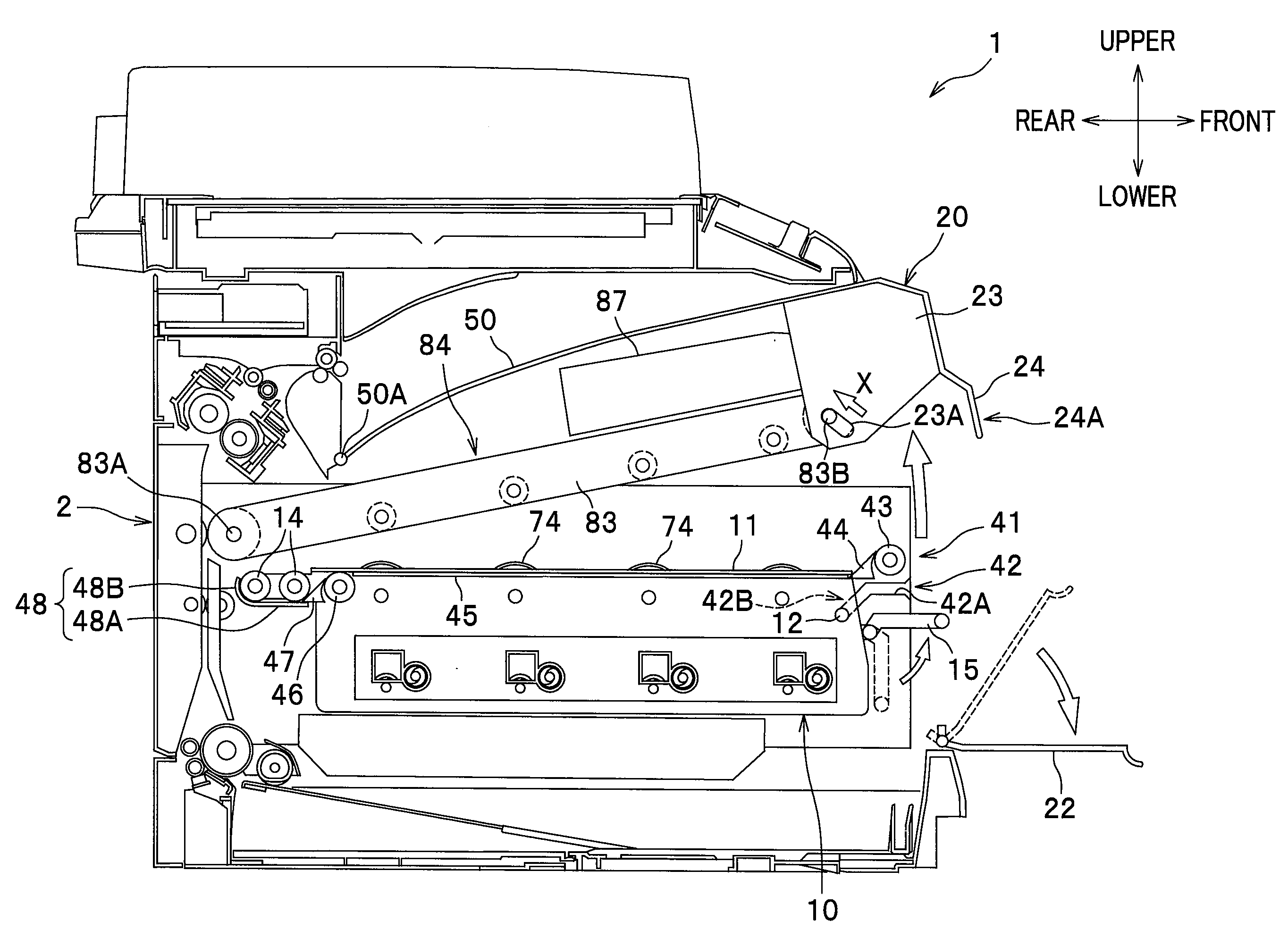
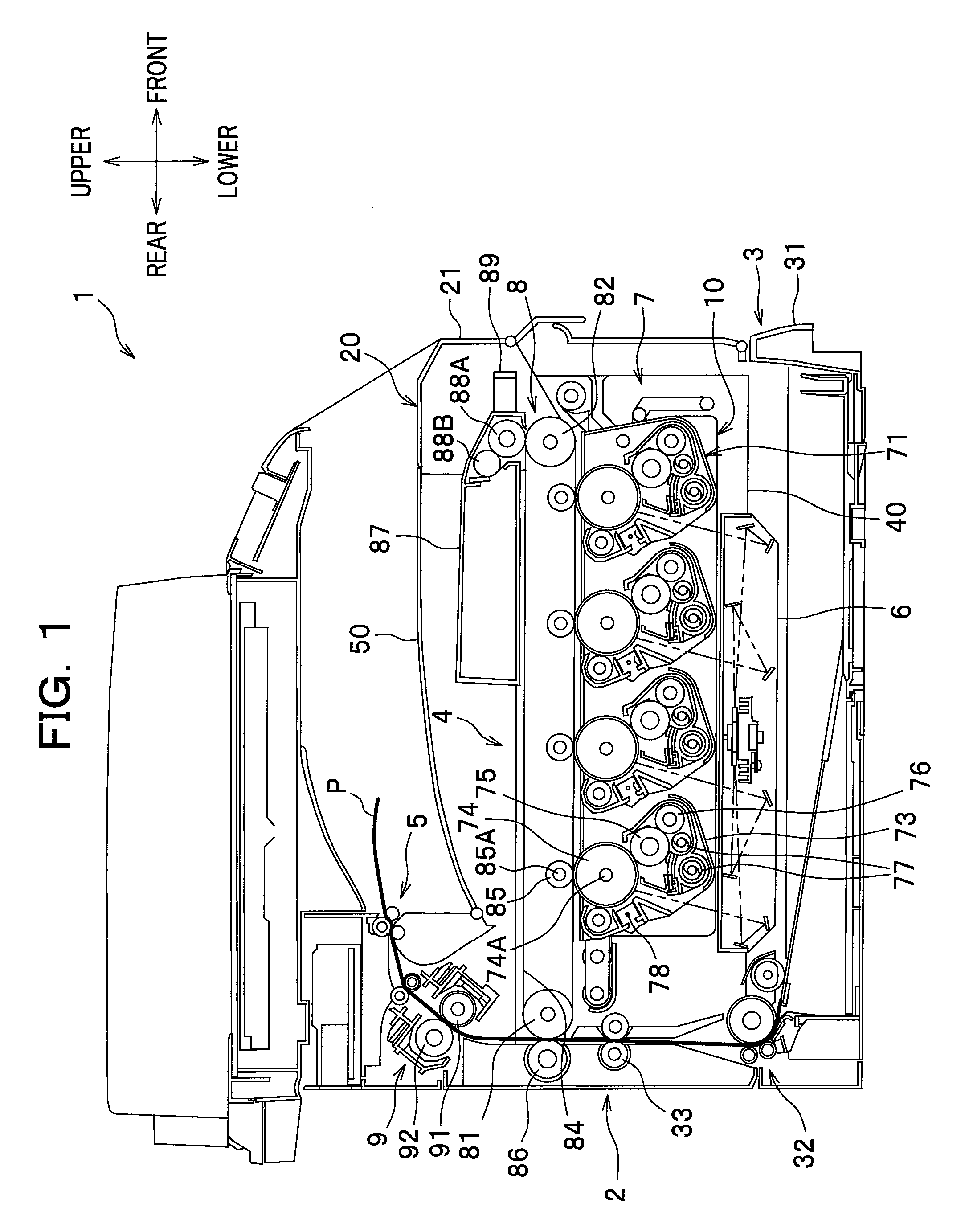
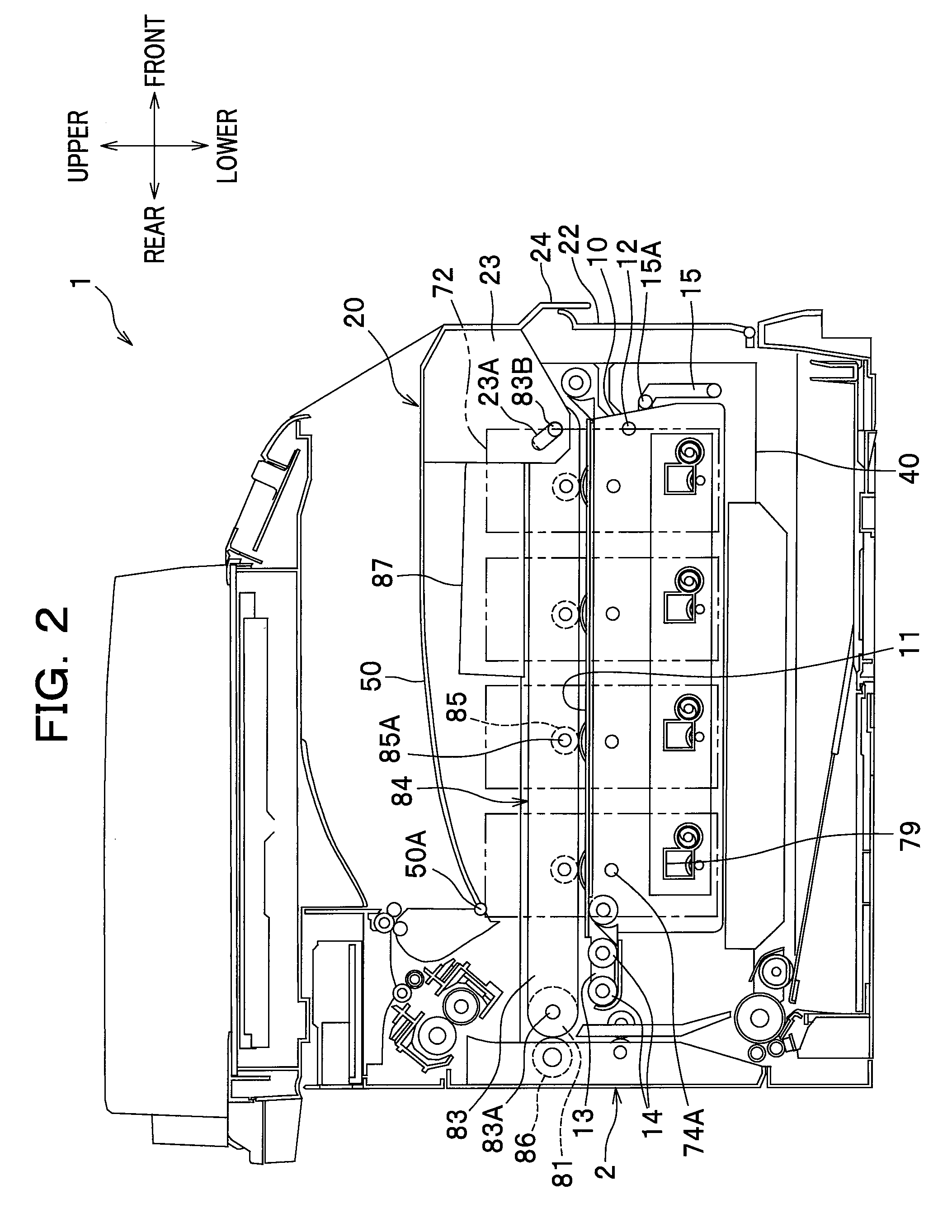
[0019]A detailed description will be given of one exemplary embodiment of the present invention with reference to the drawings. In the following description, the direction is designated as from the viewpoint of a user who is using (operating) a color printer. To be more specific, in FIG. 1, the right-hand side of the drawing sheet corresponds to the “front side” of the color printer (image forming apparatus), and the left-hand side of the drawing sheet corresponds to the “rear side” of the color printer, the front side of the drawing sheet corresponds to the “left side” of the color printer, and the back side of the drawing sheet corresponds to the “right side” of the color printer. Similarly, the direction of a line extending from top to bottom of the drawing sheet corresponds to the “vertical direction” of the printer.

[0020]As shown in FIG. 1, a color printer 1 comprises a body casing 2 which makes up a housing of a main body of the printer 1, and the main body housed within the b...


PUM


Abstract

In an image forming apparatus, a support frame is configured to support a plurality of photoconductors arranged in the apparatus, the support frame being allowed to be pulled out from a casing of the apparatus, and an intermediate transfer belt is disposed above the plurality of photoconductors and configured to be movable between a contact position in which the intermediate transfer belt is in contact with each of the plurality of photoconductors and a separate position in which the intermediate transfer belt is separate from the each of the plurality of photoconductors. A predetermined amount of upward movement of the support frame made when the intermediate transfer belt is or comes in the separate position renders the support frame operable to be pulled out in a direction of arrangement of the plurality of photoconductors.

Description

CROSS-REFERENCE TO RELATED APPLICATION(S)[0001]This application claims the foreign priority benefit under Title 35, United States Code, §119 (a)-(d), of Japanese Patent Application No. 2007-337005 filed on Dec. 27, 2007 in the Japan Patent Office, the disclosure of which is herein incorporated by reference in its entirety.BACKGROUND OF THE INVENTION[0002]1. Field of the Invention[0003]The present invention relates to an image forming apparatus which includes a support frame for supporting a plurality of photoconductors arranged in the apparatus, the support frame being allowed to be pulled out from a casing of the apparatus.[0004]2. Description of Related Art[0005]The so-called tandem type image forming apparatus typically includes a support frame for supporting a plurality of photoconductor drums arranged in a horizontal direction, wherein the support frame is allowed to be pulled out from a casing of the apparatus (e.g., through a front or side panel of the casing) so that each ph...

Claims


Application Information

Patent Timeline
Patent Type & Authority Applications(United States)
IPC IPC(8): G03G15/02G03G15/14
CPCG03G15/0131G03G21/1853G03G2221/1869G03G2221/1684G03G2215/0193G03G15/0136
Inventor SATO, SHOUGO
Owner BROTHER KOGYO KK
Why Eureka
Try Eureka