
Breathing apparatus

a technology of air passage filter and filter, which is applied in the direction of breathing mask, breathing filter, breathing protection, etc., can solve the problems of increasing the amount of air passing through the filter, excessive increase in the delay in the timing of stopping the motor fan or the decreasing rotation speed of the motor fan, so as to suppress the effect of additionally suppressing the consumption of the filter

Inactive Publication Date: 2016-08-18
SHIGEMATSU WORKS CO LTD
View PDF7 Cites 2 Cited by
  • Summary
  • Abstract
  • Description
  • Claims
  • Application Information

AI Technical Summary

Benefits of technology

The present invention provides a breathing apparatus with a positive pressure exhale valve that prevents leakage of air from the face piece during inhalation, optimizes motor fan rotation speed, and reduces filter consumption rate. The design also allows for effective use of unused holes and minimizes unnecessary air passing through the filter. These technical effects help improve the performance of the breathing apparatus.

Problems solved by technology

On the other hand, it has a disadvantage in that internal air of the face piece is apt to be discharged to the exterior through the exhale valves due to the low opening pressure of the exhale valves, so that rotation speed of the motor fan is apt to increase excessively during inhalation to compensate for leakage of air from the face piece through the exhale valves, or the timing of stopping the motor fan or the timing of decreasing rotation speed of the motor fan is apt to be delayed, due to delay of increase of the internal pressure of the face piece during transition from inhalation to exhalation.
Thus, an unnecessary amount of air passes through the filter, which increases the amount of air passing through the filter and increases the rate of filter consumption.

Method used


Image

  • Breathing apparatus
  • Breathing apparatus
  • Breathing apparatus

Examples


Embodiment Construction

[0017]A breathing apparatus in accordance with a preferred embodiment of the present invention will be described.

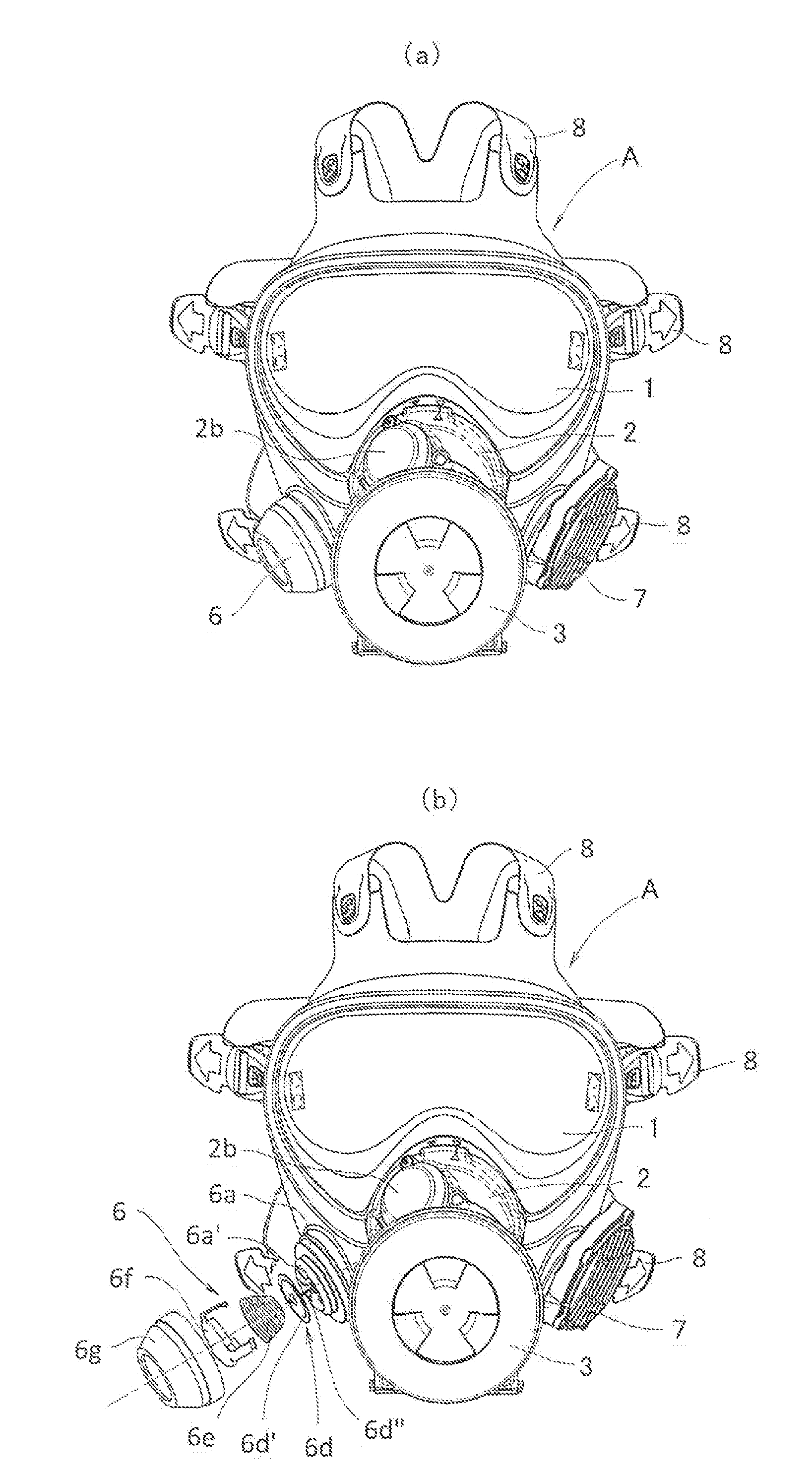
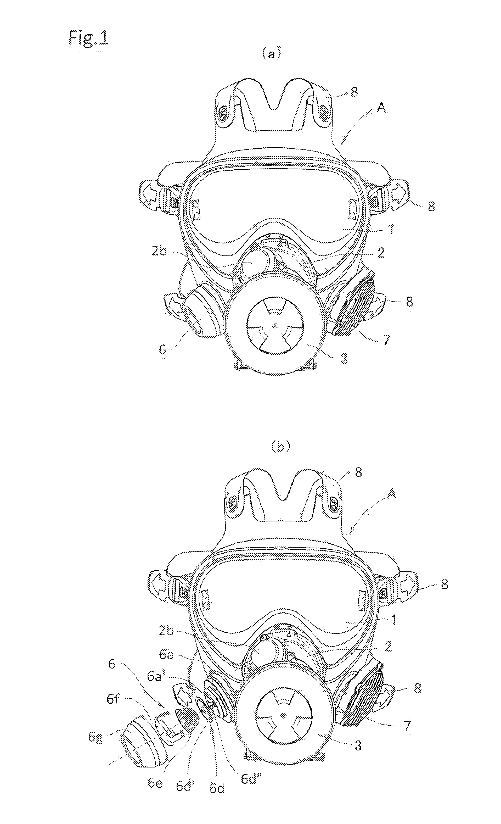
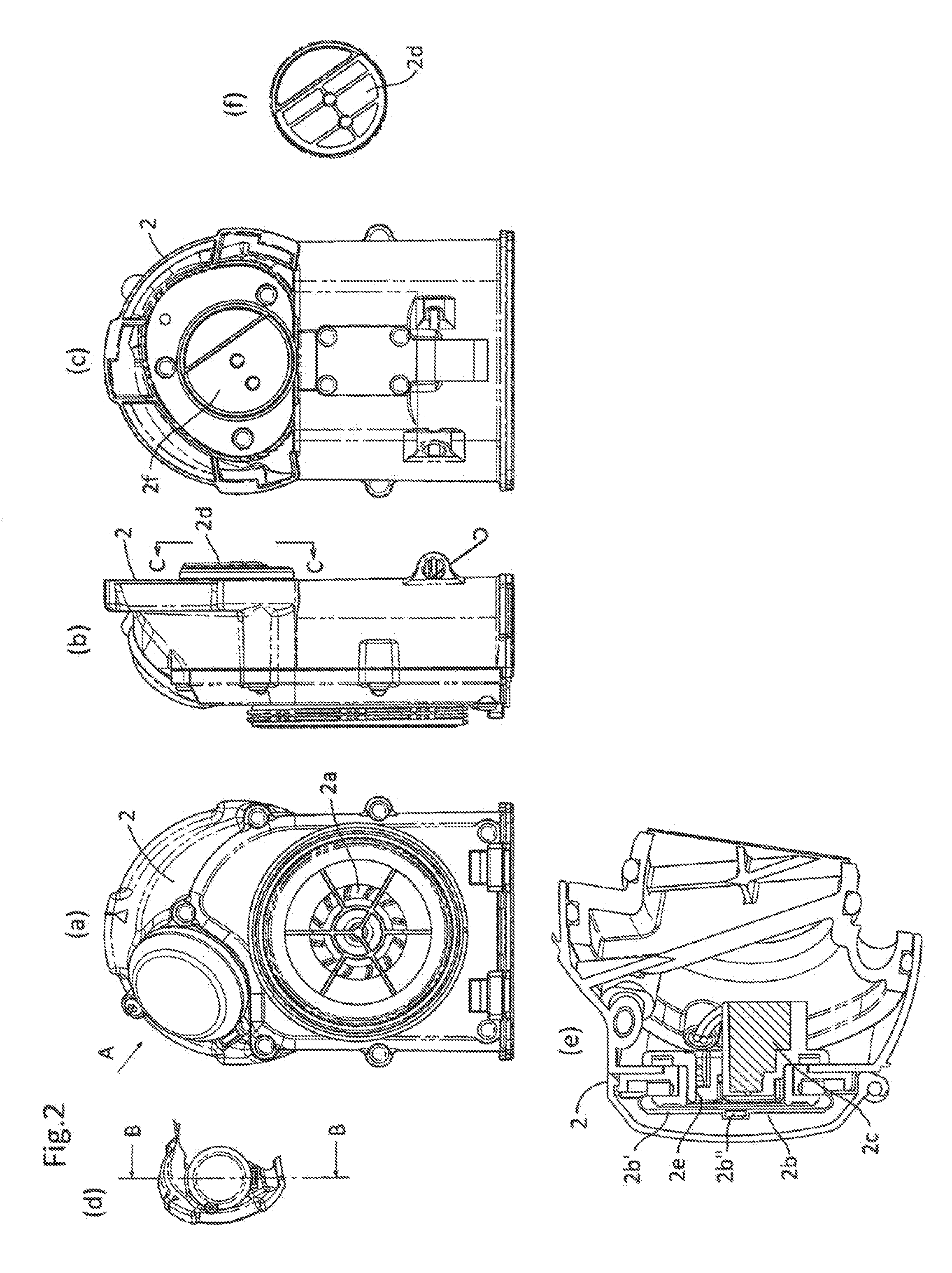
[0018]As shown in FIGS. 1 to 4, a breathing apparatus A comprises a bowl-shaped face piece 1 for covering the whole face of a user of the breathing apparatus A, a fan unit 2 detachably attached to the front surface of the face piece 1 so as to accommodate a motor fan 2a for supplying the face piece 1 with air, a pressure sensor 2b for detecting internal pressure of the face piece 1 comprising a diaphragm 2b′ and a magnetic sensor or an optical sensor 2b″, and a controller 2c for controlling the operation of the motor fan 2a based on detection signals from the pressure sensor 2b, a filter 3 detachably attached to the front surface of the fan unit 2 so as to purifying the air supplied to the face piece 1, a nose cup 4 detachably attached to the face piece 1 so as to cover a user's nose and mouth, inhale valves 5 attached to the nose cup 4 so as to communicate with an air ou...


PUM


Abstract

[Object of the Invention] An object of the present invention is to provide a breathing apparatus comprising a face piece for covering the whole face or part of the face provided with a hole at each side portion, a motor fan for supplying the face piece with external air, a pressure sensor for monitoring internal pressure of the face piece, a controller for controlling the operation of the motor fan based on a detection signal from the pressure sensor, a filter for purifying the external air supplied to the face piece, and an inhale valve and an exhale valve, wherein filter consumption is minimized.[Disclosure of the Invention] A breathing apparatus comprises a face piece for covering the whole face or part of the face provided with a hole at each side portion, a motor fan for supplying the face piece with external air, a pressure sensor for monitoring internal pressure of the face piece, a controller for controlling the operation of the motor fan based on a detection signal from the pressure sensor, a filter for purifying the external air supplied to the face piece, and an inhale valve and an exhale valve, wherein a positive pressure exhale valve is attached to one of the holes at the side portions of the face piece and a positive pressure exhale valve or a voice conductor is attached to the other of the holes at the side portions of the face piece.

Description

TECHNICAL FIELD[0001]The present invention relates to a breathing apparatus comprising a face piece for covering the whole face or part of the face provided with a hole at each side portion, a motor fan for supplying the face piece with external air, a pressure sensor for monitoring internal pressure of the face piece, a controller for controlling the operation of the motor fan based on a detection signal from the pressure sensor, a filter for purifying the external air supplied to the face piece, and an inhale valve and an exhale valve.BACKGROUND ART[0002]Patent Document No. 1 discloses a breathing apparatus comprising a face piece for covering the whole face or part of the face provided with a hole at each side portion, a motor fan for supplying the face piece with external air, a pressure sensor for monitoring internal pressure of the face piece, a controller for controlling the operation of the motor fan based on a detection signal from the pressure sensor, a filter for purifyin...

Claims


Application Information

Patent Timeline
Patent Type & Authority Applications(United States)
IPC IPC(8): A62B23/02A62B18/08A62B18/02A62B7/10A62B9/02
CPCA62B23/025A62B7/10A62B18/084A62B18/02A62B18/025A62B9/02
Inventor ONO, KENICHIIDE, HIROYUKISANTOU, GENTA
Owner SHIGEMATSU WORKS CO LTD
Learn More