Electric Door Lock

a door lock and electric technology, applied in the field of door locks, can solve the problems of unnecessarily including the manual operating member of the door lock, and increasing the production cos

Inactive Publication Date: 2009-07-09
LONG CYUAN
View PDF10 Cites 12 Cited by
  • Summary
  • Abstract
  • Description
  • Claims
  • Application Information

AI Technical Summary

Benefits of technology

[0008]According to an aspect of the present invention, an electric door lock comprises a lock housing, a driving module, and control module. The driving module is mounted in the lock housing, and is operable between locking and unlocking modes. The control module includes a switch unit and a manual operating member. The switch unit is mounted in the lock housing, is coupled to the driving module, and is operable so as to deactivate the driving module when actuated. The manual operating member includes a shaft. The shaft extends rotatably into the lock housing, has an outer surface formed with at least one actuating protrusion, and is rotatable relative to the lock housing between locking and unlocking positions. When the driving module is operated in the locking mode, the shaft of the manual operating member is disposed at the locking position and the actuating protrusion actuates the switch unit. When the driving module is operated in the unlocking mode, the shaft of the manual operating member is disposed at the unlocking position and the actuating protrusion actuates the switch unit.
[0009]According to another aspect of the present invention, a control module for an electric door lock comprises a switch unit and a manual operating member. The electric door lock includes a lock housing, and a driving module that is mounted in the lock housing and that is operable between locking and unlocking modes. The switch unit is adapted to be mounted in the lock housing and to be coupled to the driving module. The switch unit is operable so as to deactivate the driving module when actuated. The manual operating member includes a shaft. The shaft is adapted to extend rotatably into the lock housing, has an outer surface formed with at least one actuating protrusion, and is rotatable relative to the lock housing between locking and unlocking positions. When the driving module is operated in the locking mode, the shaft of the manual operating member is disposed at the locking position and the actuating protrusion actuates the switch unit. When the driving module is operated in the unlocking mode, the shaft of the manual operating member is disposed at the unlocking position and the actuating protrusion actuates the switch unit.

Problems solved by technology

Although the aforementioned conventional electric door lock achieves its intended purpose, the manual operating member thereof unnecessarily includes the plate 134.
This gives rise to higher production costs.

Method used


Image

  • Electric Door Lock
  • Electric Door Lock
  • Electric Door Lock

Examples


Embodiment Construction

[0016]Before the present invention is described in greater detail, it should be noted that like elements are denoted by the same reference numerals throughout the disclosure.

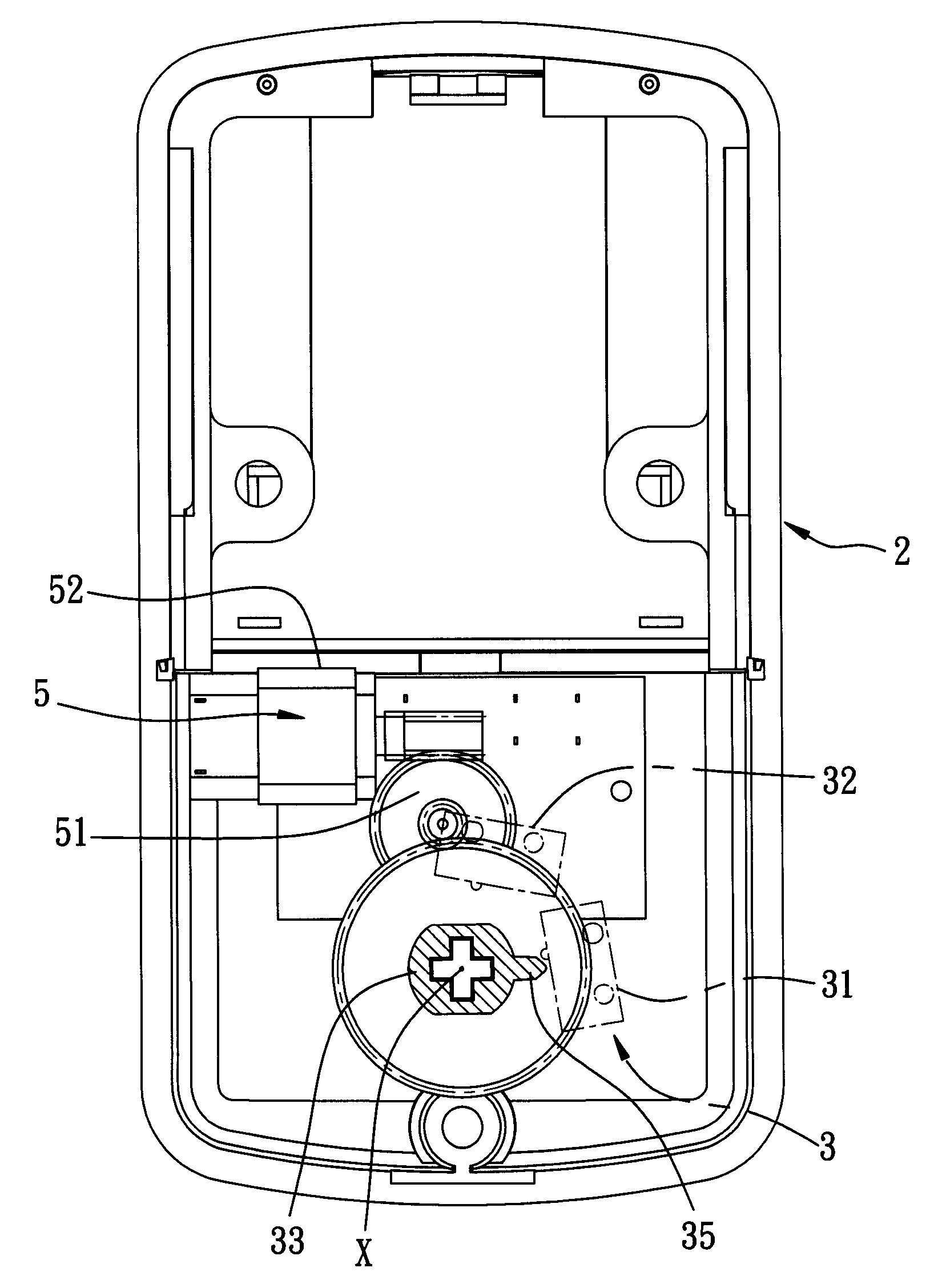
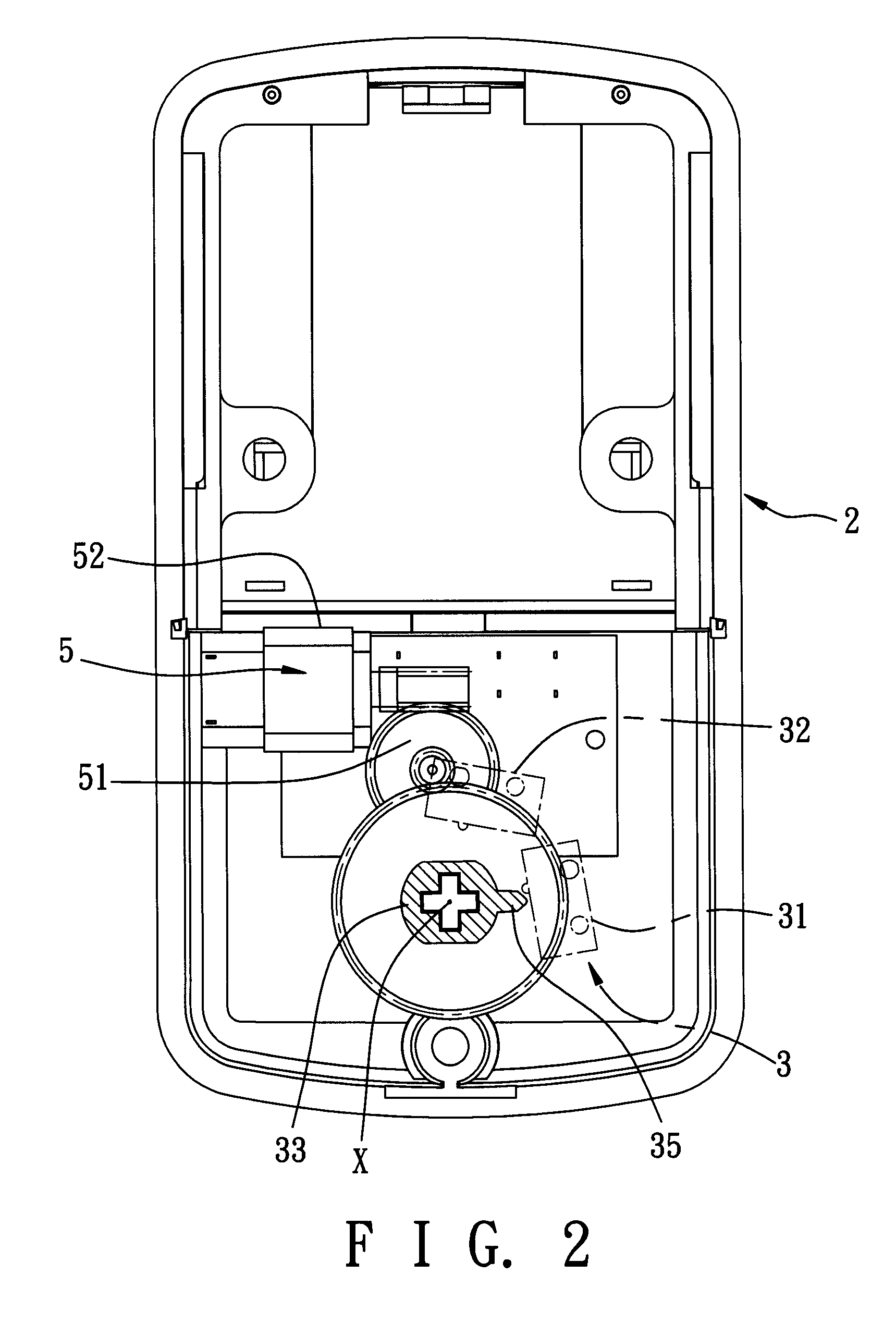
[0017]Referring to FIG. 2, the first preferred embodiment of an electric door lock according to this invention is shown to include a lock housing 2, a driving module 5, and a control module 3.

[0018]The lock housing 2 defines an axis (X).

[0019]The driving module 5 is operable in locking and unlocking modes. In particular, the driving module 5 includes a gear assembly 51 and a motor 52. The gear assembly 51 is mounted rotatably in the lock housing 2. The motor 52 is mounted in the lock housing 2, is coupled to the gear assembly 51, and is operable so as to drive rotation of the gear assembly 51. The gear assembly 51 is rotatable relative to the lock housing 2 in a first rotational direction when the driving module 5 is operated in the locking mode, and a second rotational direction opposite to the first rotational...


PUM


Abstract

An electric door lock includes a driving module and a control module. The driving module is operable between locking and unlocking modes. The control module includes a switch unit and a manual operating member. The switch unit is operable so as to deactivate the driving module when actuated. The manual operating member includes a shaft that extends rotatably into the lock housing, that has an actuating protrusion, and that is rotatable relative to the lock housing between locking and unlocking positions. When the driving module is operated in the locking mode, the shaft of the manual operating member is disposed at the locking position and the actuating protrusion actuates the switch unit. When the driving module is operated in the unlocking mode, the shaft of the manual operating member is disposed at the unlocking position and the actuating protrusion actuates the switch unit.

Description

BACKGROUND OF THE INVENTION[0001]1. Field of the Invention[0002]This invention relates to a door lock, more particularly to an electric door lock.[0003]2. Description of the Related Art[0004]In Taiwanese Patent Application Publication No. 475640, there is disclosed a conventional electric door lock, as illustrated in FIG. 1. The conventional electric door lock includes a lock housing 11, a driving module 12, and a control module 13. The driving module 12 is operable between locking and unlocking modes. In particular, the driving module 12 includes a gear assembly 121 and a motor 122. The gear assembly 121 is mounted rotatably in the lock housing 11. The motor 122 is mounted in the lock housing 11, is coupled to the gear assembly 121, and is operable so as to drive rotation of the gear assembly 121. The gear assembly 121 is rotatable relative to the lock housing 11 in a first rotational direction when the driving module 12 is operated in the locking mode, and a second rotational dire...

Claims


Application Information

Patent Timeline
Patent Type & Authority Applications(United States)
IPC IPC(8): E05B47/02E05B65/00
CPCE05B47/0012E05B2047/0091E05B2047/002E05B2047/0017Y10T70/5155
Inventor LIN, LUNG-YINFAN, CHUAN-TIEN
Owner LONG CYUAN
Why Eureka
Try Eureka