Nailing device

Active Publication Date: 2007-01-25
HAMAR DOUGLAS J
View PDF15 Cites 17 Cited by
  • Summary
  • Abstract
  • Description
  • Claims
  • Application Information

AI Technical Summary

Problems solved by technology

Installing flooring can be a very time consuming and labor intensive process.
Further, when installing a wood floor, it is undesirable to have any marks on the top surface of the floor from the component securing the floor to the subfloor.
Again, this is a time consuming process where the nailer device must be placed along the edge of the floorboard so that the securing component can be driven through the floor

Method used


Image

  • Nailing device
  • Nailing device
  • Nailing device

Examples


Embodiment Construction

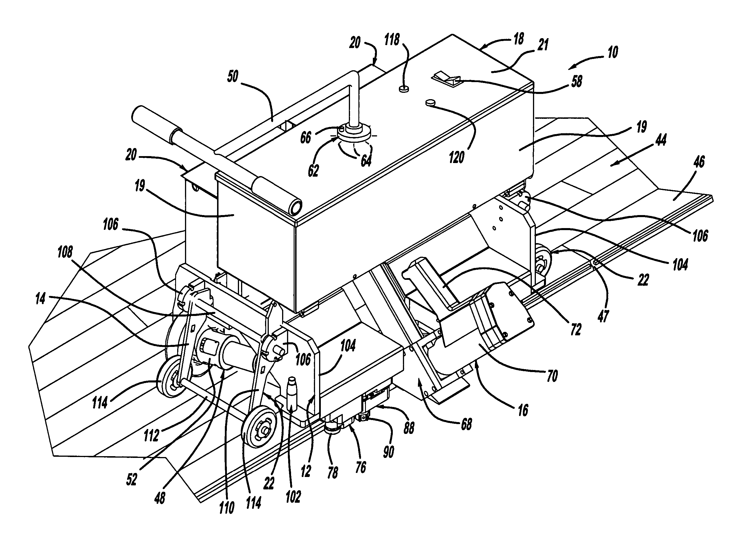
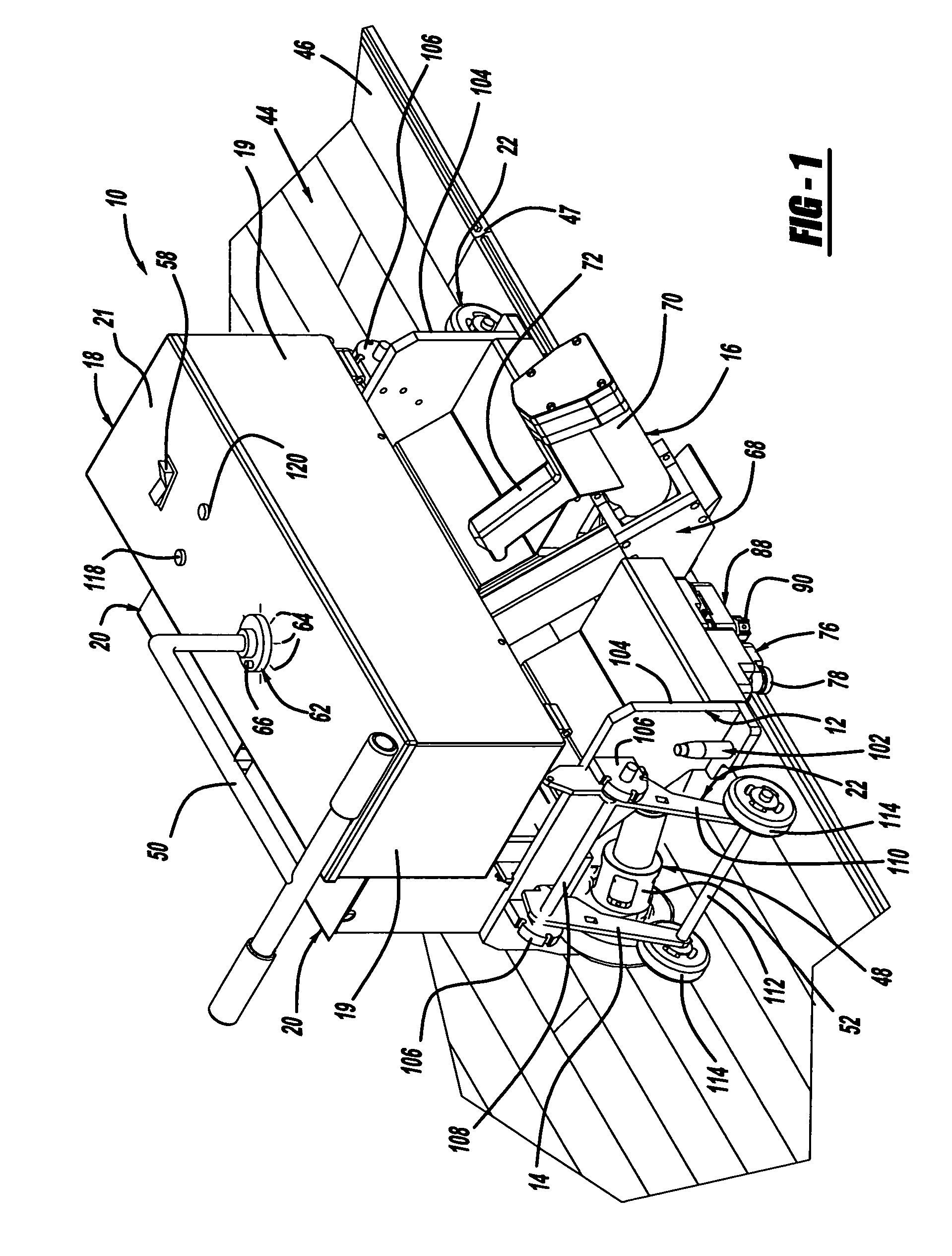
[0022] A nailing device is generally shown at 10 in FIG. 1. The nailing device is particularly adapted for driving fasteners such as, for example, nails or staples into flooring material, preferably tongue-and-groove hardwood material. The flooring material is preferably tongue-and-groove flooring that is secured to a support structure. The support structure can comprise a subfloor of suitable material or a plurality of sleepers, as are well known in the art. It will be appreciated that the support structure can comprise any suitable structure.

[0023] The nailing device 10 includes a carriage assembly generally indicated at 12. The carriage assembly 12 supports drive wheels 14. The carriage assembly 12 also supports a nailer assembly generally indicated at 16. The carriage assembly 12 further supports a programmable logic chip (PLC) housing generally indicated at 18 and a pair of battery housing generally indicated at 20. Further, the carriage assembly 12 supports a pair of end whee...


PUM

PropertyMeasurementUnit
Angleaaaaaaaaaa
Heightaaaaaaaaaa

Abstract

A nailer device having a carriage assembly, a pair of pivotal drive wheels, a nailer assembly and at least one end wheel. The pair of pivotal drive wheels are on the carriage assembly. The at least one end wheel is disposed adjacent an end of the carriage assembly. A drive motor can be associated with at least one of the pair of pivotal drive wheels when the nailer device is operating in an automatic mode. A handle disposed either intermediate of the pivotal drive wheels can be used to move or manually operate the nailer device and move the nailer device to an adjacent row of floorboards to be secured. A pair of adjustable wheels is also provided to adjust the height of the device.

Description

CROSS-REFERENCE TO RELATED APPLICATION [0001] The instant application claims priority to U.S. Provisional Patent Application Ser. No. 60 / 701,095 filed Jul. 20, 2005 the entire specification of which is expressly incorporated herein by reference.FIELD OF THE INVENTION [0002] The present invention relates to a nailing device for driving fasteners into flooring material. BACKGROUND OF THE INVENTION [0003] Installing flooring can be a very time consuming and labor intensive process. This is especially true when the flooring being installed is a wood floor which has to be installed using individual boards which typically interlock with one another and are secured to a subfloor. Typically, the panels of wood floors have a groove extending longitudinally along a side of the board and groove extending longitudinally along the opposite side of the board so that the tongue of one board is accepted by the groove of an adjacent board. [0004] Further, when installing a wood floor, it is undesira...

Claims


Application Information

Patent Timeline
IPC IPC(8): B21J15/28
CPCB27F7/02
Inventor HAMAR, DOUGLAS J.
Owner HAMAR DOUGLAS J
Why Eureka
Try Eureka