Drive arrangement for a motor vehicle

a technology for driving arrangements and motor vehicles, applied in the direction of machines/engines, process and machine control, instruments, etc., can solve the problems of inability to achieve continuous operation, reduced fuel consumption, and low output, so as to increase the wheel-driving torque, reduce the wheel-driving output, and increase the speed

Inactive Publication Date: 2000-05-09
ZF FRIEDRICHSHAFEN AG
View PDF22 Cites 129 Cited by
  • Summary
  • Abstract
  • Description
  • Claims
  • Application Information

AI Technical Summary

Benefits of technology

As previously mentioned, a second electric machine can be connected mechanically in parallel with the internal combustion engine, and hence connected to the first torque transmission path. The second electric machine is expediently used both as a motor and as a generator. In the case of operation as a generator, the second electric machine may be used in the entire driving speed range of the motor vehicle for charging a battery of the motor vehicle that supplies a driving current. Below the speed limit, e.g. in the first operating state, the generator current can also drive the first electric machine directly. In motor operation, the second electric machine may be used to start the internal combustion engine. In particular, however, the second electric machine increases the wheel-driving torque supplied by the internal combus...

Problems solved by technology

However, in the case of serial hybrid drives, the overall fuel consumption may be reduced only to a limited extent, and the output that is available in continuous operation is comparatively low.
production boundary conditions such as cost and weight it is not possible with the current status of electric motor technology to implement driving outputs, as for example starting torque, maximum output, and maximum speed to match that of a powerful conventional drive.
Furthermore, hybrid drives that can be operated in several modes of operation are known, in which the internal combustion engine and an electric machine that can be operated both as a generator and as a motor are connected to the driving whe...

Method used


Image

  • Drive arrangement for a motor vehicle
  • Drive arrangement for a motor vehicle

Examples


Embodiment Construction

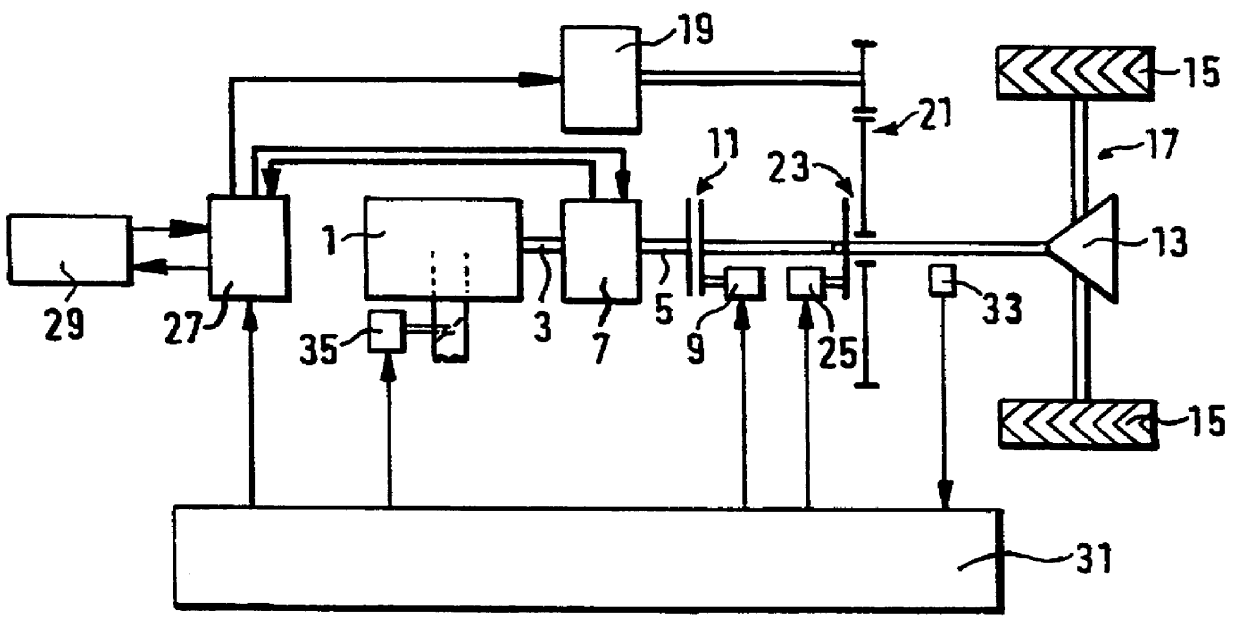
The hybrid drive shown schematically as a block diagram in FIG. 1 comprises an internal combustion engine 1, whose output shaft 3 is equiaxially and fixedly connected to the output shaft 5 of an electric machine 7 that can be operated both as a generator and as a motor. Via a clutch 11, for example a friction clutch, that can be actuated by means of an actuator 9, the unit formed from the internal combustion engine 1 and the electric machine 7 is connected to a differential transmission 13 of a drive axle unit 17, comprising driving wheels 15, of the motor vehicle. With the clutch 11 engaged, a first torque transmission path starts, via the output shafts 3, 5, the clutch 11 and the reducing differential transmission 13, from the internal combustion engine 1 and the electric machine 7 that is mechanically connected in parallel thereto, to the driving wheels 15.

The drive axle unit 17 can also be driven by another electric machine 19, operating as a motor, which is connected to the inp...


PUM


Abstract

A hybrid drive arrangement for a motor vehicle including an internal combustion engine (1), which is connected or can be connected in a wheel-driving manner, via a first torque transmission path (11, 13), to a driving wheel (15) of the motor vehicle. An electric machine (19), which is operable at least as a motor, is fed from an electrical energy source (7, 29) of the motor vehicle and is connected or can be connected in a wheel-driving manner, via a second torque transmission path (21, 23, 13), to the driving wheel (15). Arranged in the first and/or the second torque transmission path are coupling elements (11, 23) which, in a first operating state, permit the driving of the motor vehicle by the wheel-driving torque of the electric machine (19), operated as a motor, without mechanical torque support from the internal combustion engine (1), and which, in a second operating state, permit the driving of the motor vehicle by the internal combustion engine (1), without mechanical torque support from the electric machine (19). Depending on the driving speed of the motor vehicle, an electronic driving control system (31) activates the first operating state, at least in a first range of driving speeds including standstill of the vehicle, if the driving speed is less than a predetermined speed limit, and activates the second operating state, at least in a second range including the maximum speed of the vehicle, if the driving speed is greater.

Description

BACKGROUND OF THE INVENTION1. Field of the InventionThe present invention relates to a hybrid drive for a non-railbound motor vehicle, which can be driven both by wheel-driving torque from an internal combustion engine and wheel-driving torque from an electric machine operated as a motor.2. Description of the Related ArtThere are different types of hybrid drives for motor vehicles. Serial hybrid drives feed the electric motor driving the driving wheels from a generator, which for its part is driven by the internal combustion engine of the motor vehicle. In this way, the internal combustion engine can be operated in a region of its characteristic map that is selected from the point of view of reducing the energy consumption and reducing pollutant emission. However, in the case of serial hybrid drives, the overall fuel consumption may be reduced only to a limited extent, and the output that is available in continuous operation is comparatively low. Under massproduction boundary condit...

Claims


Application Information

Patent Timeline
IPC IPC(8): B60K6/00B60K6/04B60K1/00B60K1/02B60K17/04B60K6/442B60L50/16B60W10/02B60W10/08B60W20/00F02D29/02
CPCB60W10/02B60W10/08B60K6/442B60K1/02B60L2200/26B60W20/00B60W2520/10Y02T10/6234Y10S903/903Y10S903/951Y10S903/905Y10S903/909Y10S903/946Y10S903/906Y10S903/914F16H2312/02Y02T10/62B60W30/18063
Inventor SCHMIDT-BRUCKEN, HANS-JOACHIM
Owner ZF FRIEDRICHSHAFEN AG
Why Eureka
Try Eureka