

Wheel set for robot cleaner
- Summary
- Abstract
- Description
- Claims
- Application Information
AI Technical Summary
Benefits of technology
Problems solved by technology
Method used
Image

Examples
Embodiment Construction
[0008]In order to achieve the aforementioned object, the present invention provides a preferred embodiment described in accompany with the drawings as below.
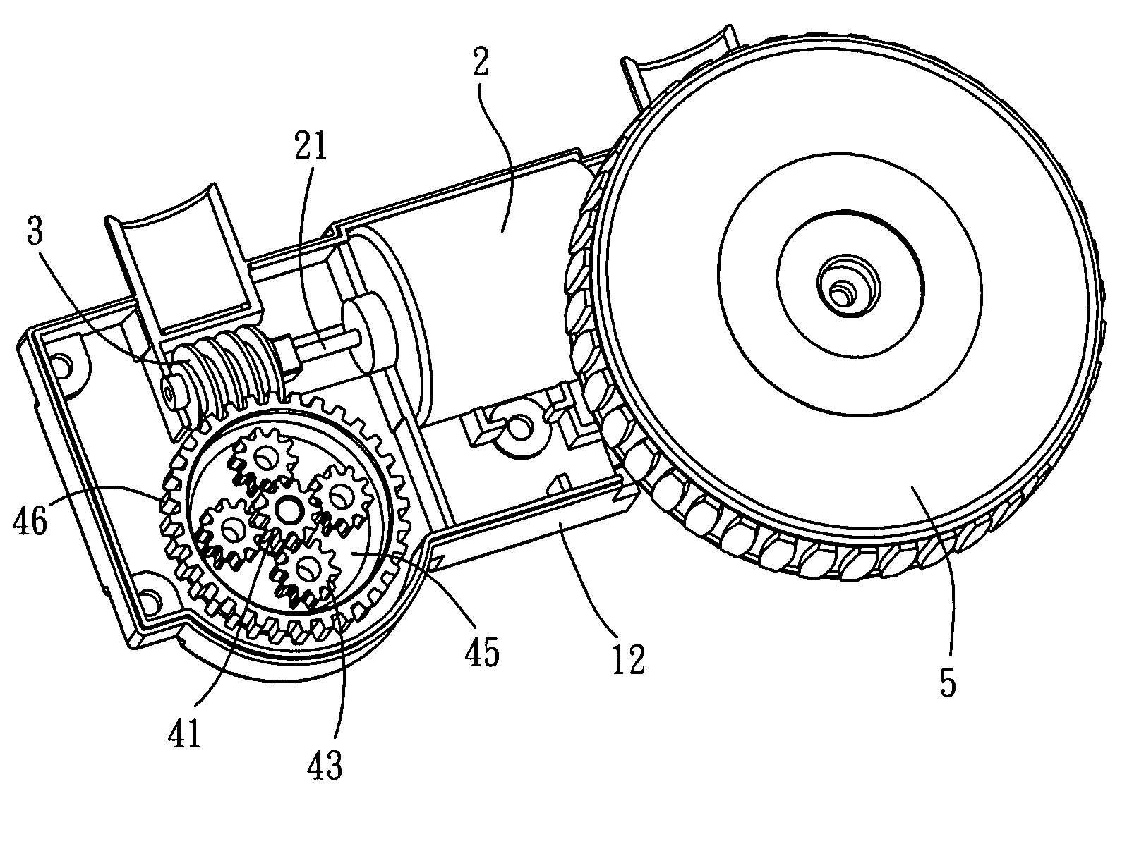
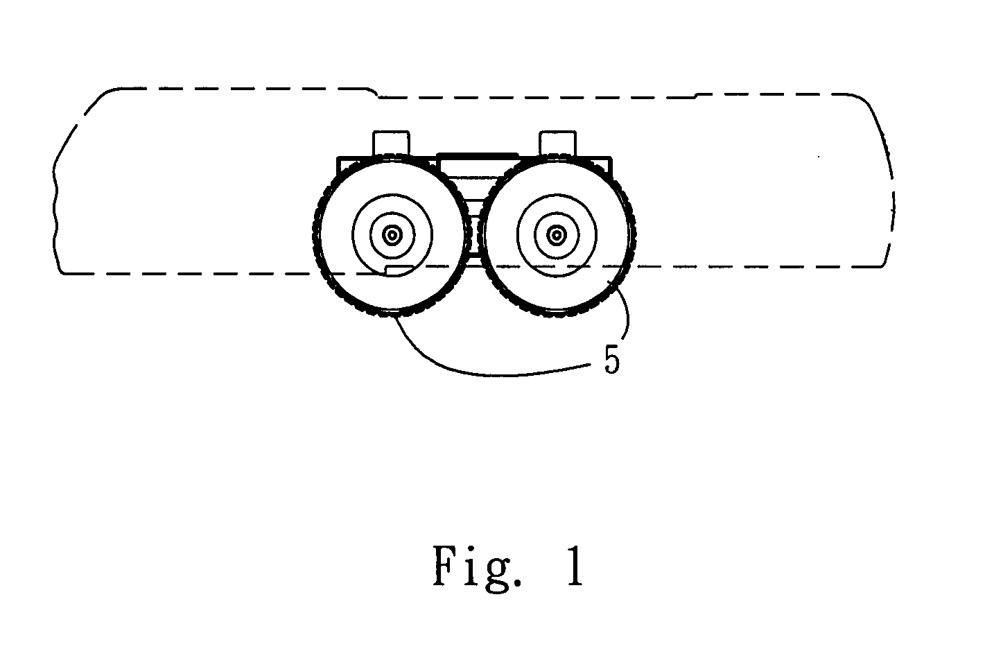
[0009]Referring to FIG. 1, the wheel set for robot cleaner in accordance with the present invention is installed under the main body of a robot cleaner for supporting the robot cleaner to move on a floor. The wheel set comprises two driving wheels, with one driving wheel at either side of the robot cleaner. The robot cleaner further comprises controller circuits, sensors and vacuum devices, which are not the content of the present invention and will not be described in detail.
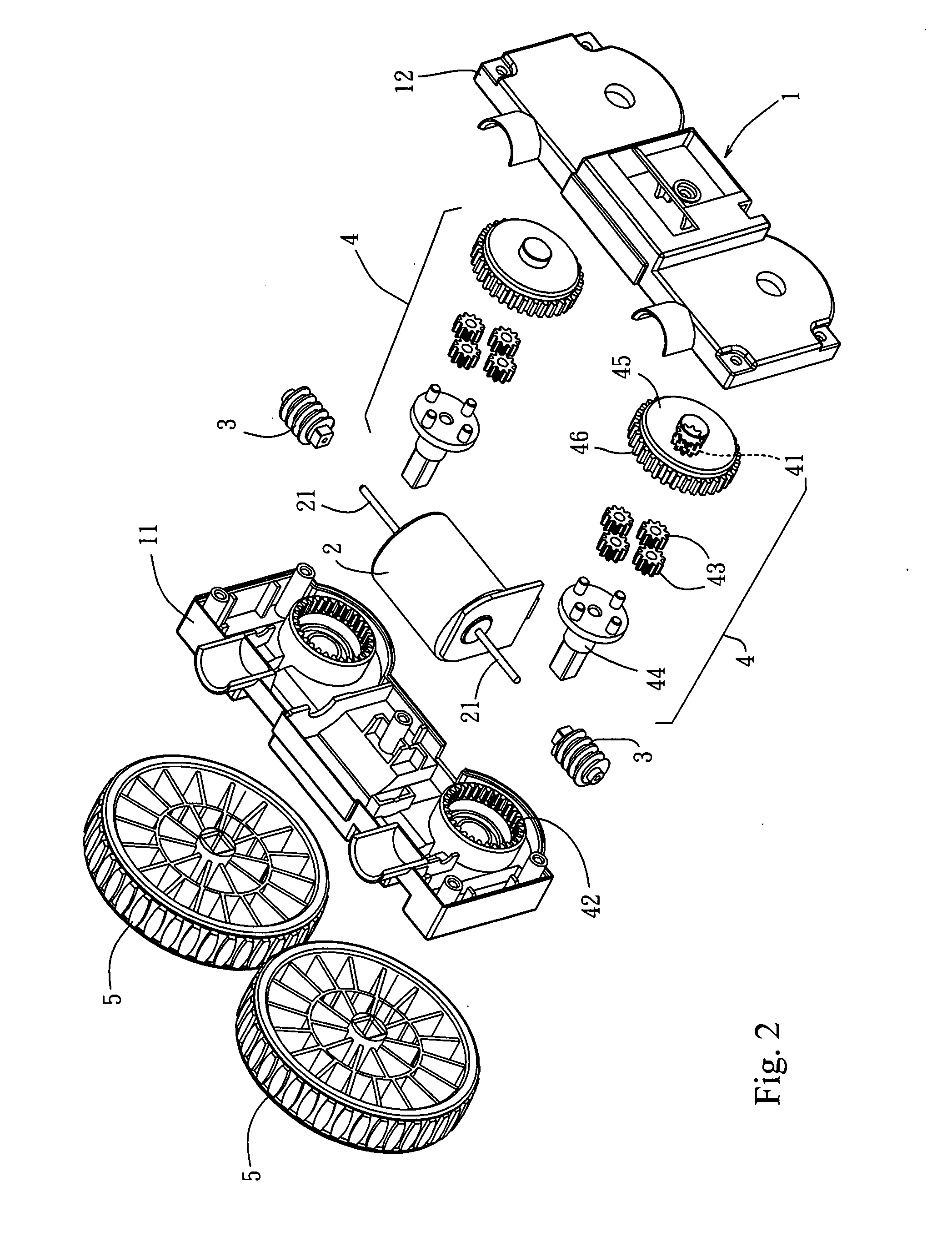
[0010]Referring to FIG. 2, in which one driving wheel at one side of the robot cleaner is shown, it comprises a housing 1, a motor 2 (power source), two transmission mechanisms and two wheels 5.
[0011]The housing 1 includes a first shell 11 and a second shell 12 to form an accommodating space to install devices stated below.
[0012]The motor 2 is placed in the...
PUM
 Abstract
Description
Claims
Application Information