Information display and method of displaying information for a vehicle

a technology of information display and vehicle, which is applied in the directions of instruments, transportation and packaging, structural/machine measurement, etc., can solve the problem that the display device described in kondo does not provide a schematic representation of the vehicl

a technology of information display and vehicle, which is applied in the directions of instruments, transportation and packaging, structural/machine measurement, etc., can solve the problem that the display device described in kondo does not provide a schematic representation of the vehicl

US20070208468A1Inactive Publication Date: 2007-09-06FORD MOTOR CO

Image

  • Information display and method of displaying information for a vehicle
  • Information display and method of displaying information for a vehicle
  • Information display and method of displaying information for a vehicle

Examples


Embodiment Construction

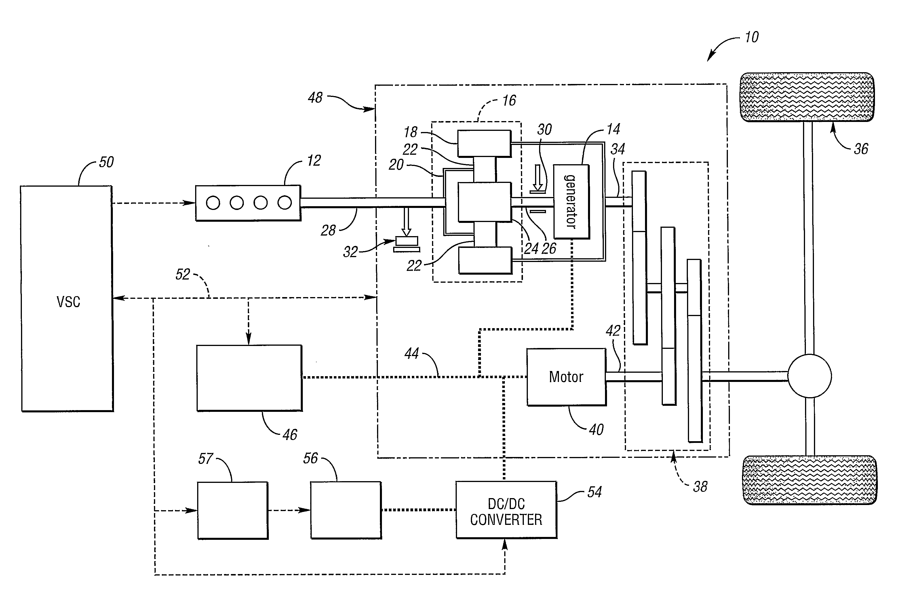
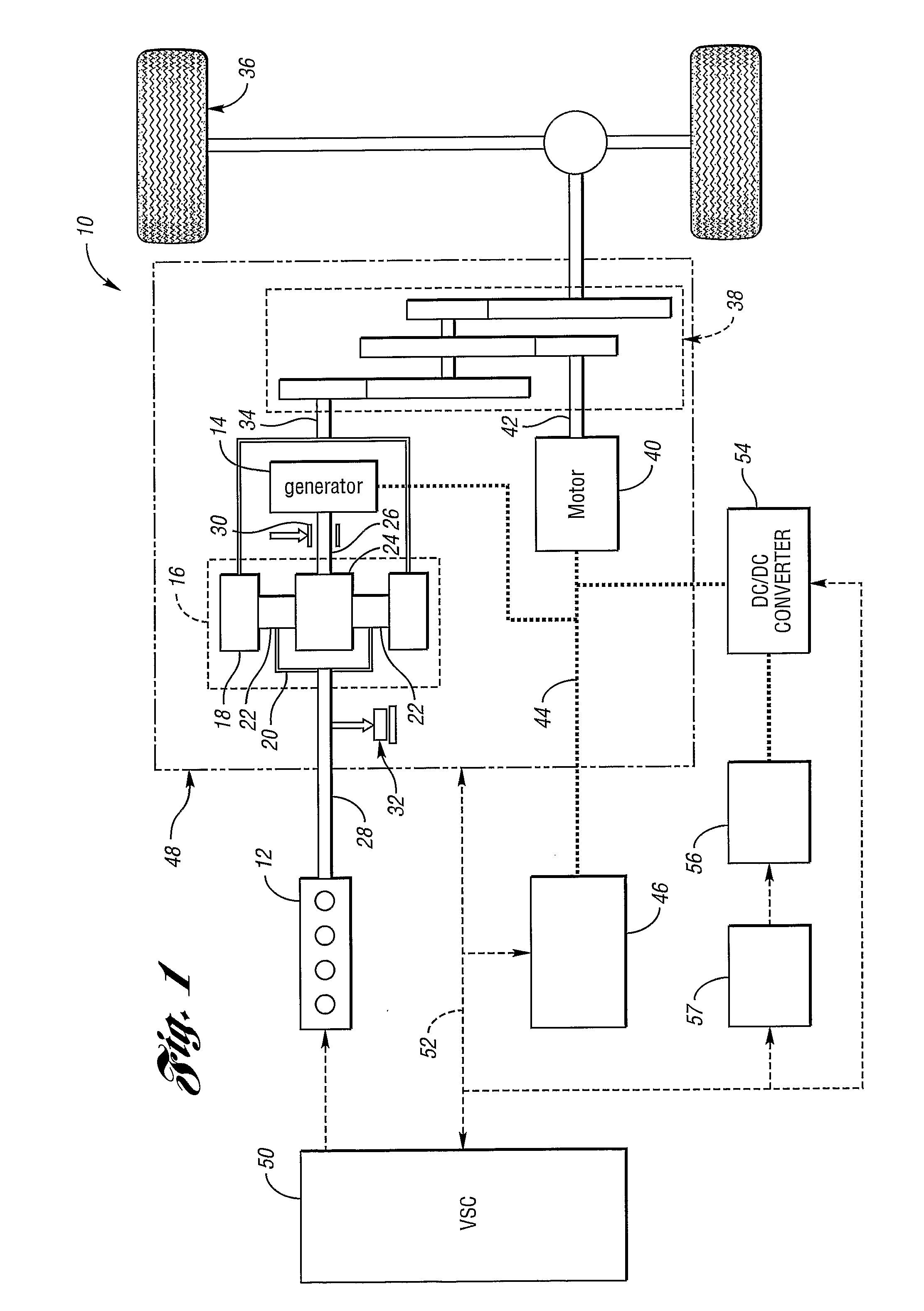
[0022]FIG. 1 shows a schematic representation of a vehicle 10 in accordance with the present invention. Although the vehicle 10 is an HEV, other types of vehicles are within the scope of the present invention—e.g., fuel cell vehicles, hybrid fuel cell vehicles, and pure electric vehicles. The vehicle 10 includes an engine 12 and a generator 14. The engine 12 and the generator 14 are connected through a power transfer unit, which in this embodiment is a planetary gear set 16. Of course, other types of power transfer units, including other gear sets and transmissions may be used to connect the engine 12 to the generator 14. The planetary gear set includes a ring gear 18, a carrier 20, planet gears 22, and a sun gear 24.

[0023] The generator 14 can also be used as a motor, outputting torque to a shaft 26 connected to the sun gear 24. Similarly, the engine 12 outputs torque to a shaft 28 connected to the carrier 20. A brake 30 is provided for stopping rotation of the shaft 26, thereby l...


PUM


Abstract

A vehicle information display (56) for a hybrid electric vehicle is provided. The display (56) includes an engine icon (60), a motor icon (62), a battery icon (64) and a vehicle drive wheels icon (66). To provide information to the vehicle operator regarding the operating state of the vehicle, power flow indicators (68, 70, 72) between the various icons are used to indicate the direction and magnitude of power flow between corresponding components of the vehicle.

Description

BACKGROUND OF THE INVENTION [0001] 1. Field of the Invention [0002] The present invention relates to an information display and a method of displaying information for a vehicle. [0003] 2. Background Art [0004] Conventional vehicles, such as those powered by a single internal combustion engine, often provide a vehicle operator with information through a number of commonly used displays. For example, speedometers, odometers, tachometers, fuel level gauges, oil level indicators and engine temperature gauges are commonly used to provide information in analog and / or digital form. With the increase in prevalence of non-conventional vehicles—e.g., fuel cell vehicles and hybrid electric vehicles (HEV)—a need has arisen to provide a vehicle operator with additional information unique to these non-conventional vehicles. [0005] A vehicle having both an engine and a motor may be powered by either one or both of these torque-producing devices. In addition, the electric motor may act as a generat...

Claims


Application Information

Patent Timeline
06 Sep 2007
Publication
US20070208468A1
IPC
G01M17/00; B60K6/20; B60K6/445; B60K6/448; B60K35/00
CPC
B60K6/445; B60K6/448; B60K35/00; Y02T10/6239; B60Y2200/90; Y02T10/6243; B60K2350/2008; Y02T10/62
Inventors
SANKARAN, VENKATESWA; CHORIAN, STEVEN