

Clock recovery circuit
- Summary
- Abstract
- Description
- Claims
- Application Information
AI Technical Summary
Benefits of technology
Problems solved by technology
Method used
Image

Examples
Embodiment Construction
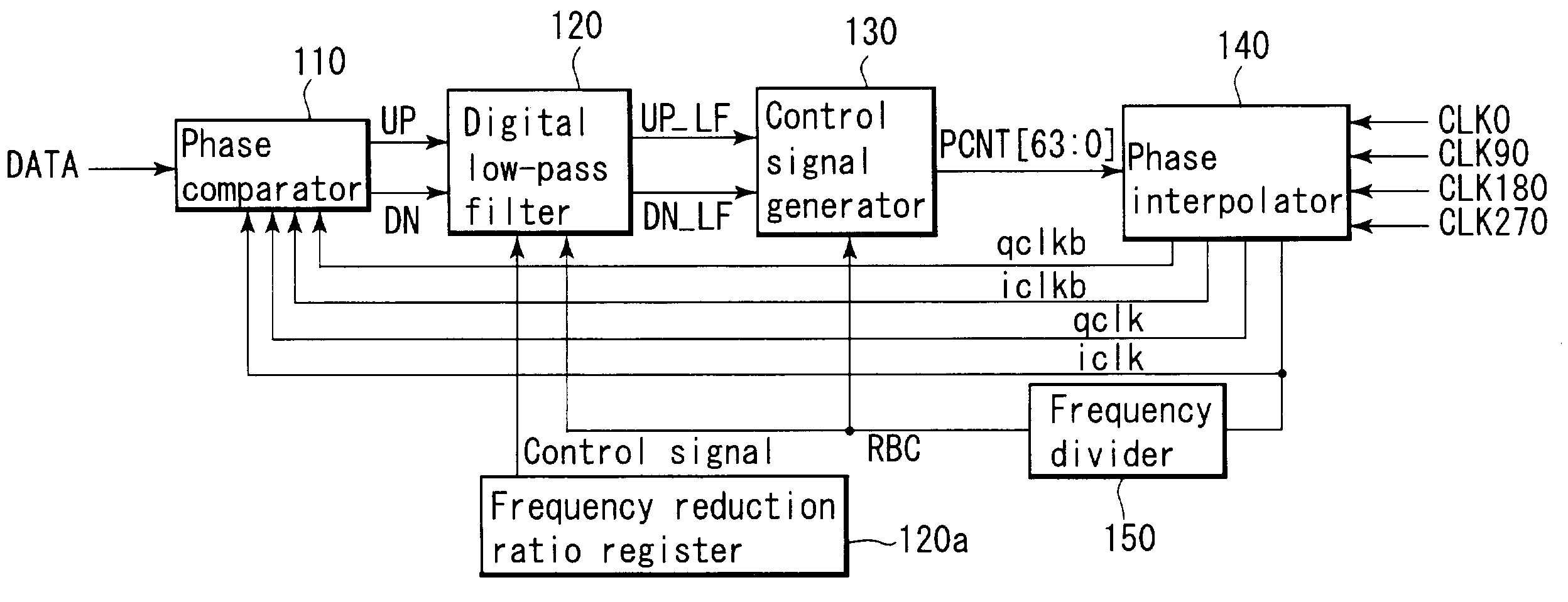
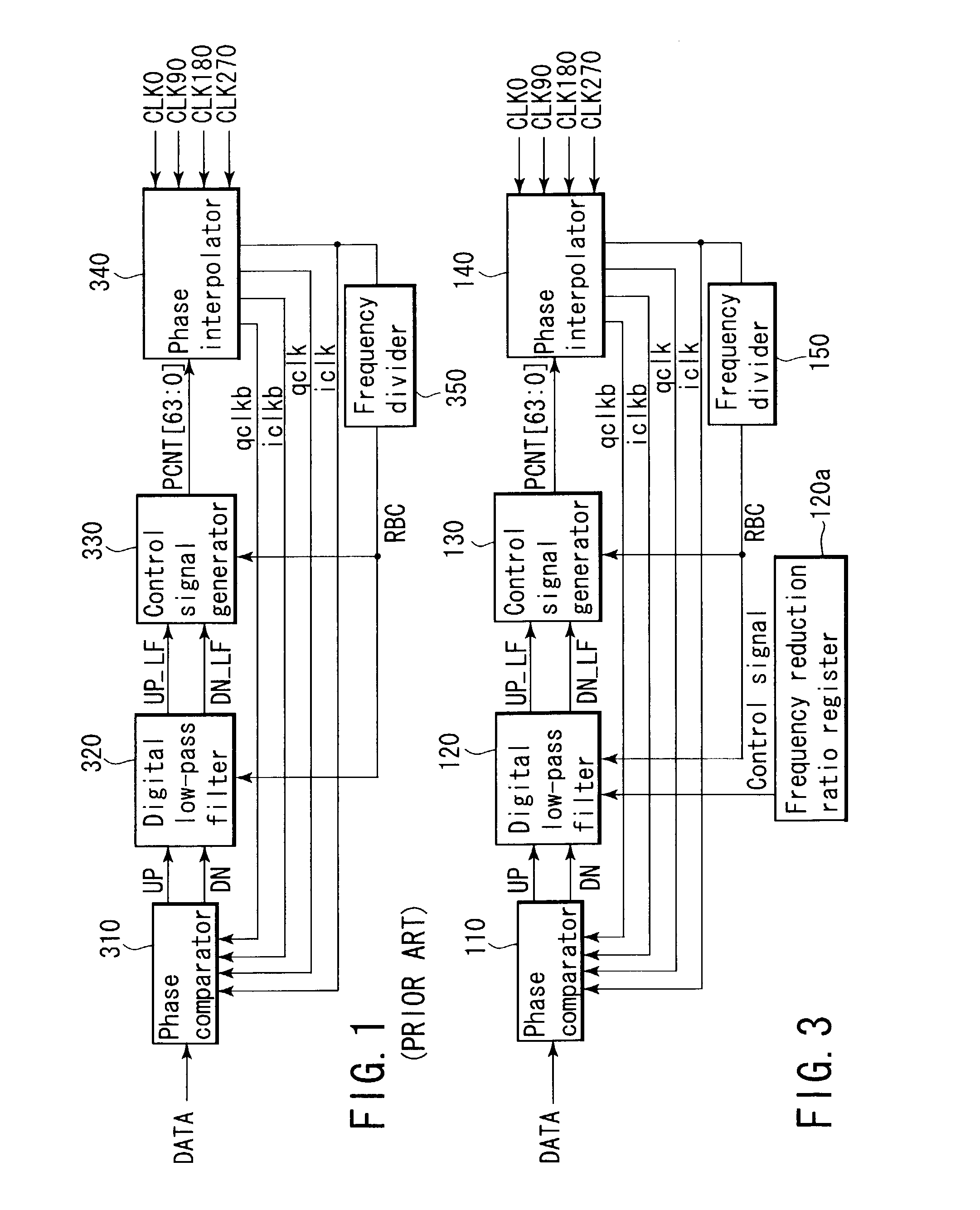
[0027]Before explaining an embodiment, problems in the conventional clock recovery circuit will be first described. FIG. 1 shows an example of a conventional clock recovery circuit using multiphase clocks. In FIG. 1, reference numeral 310 denotes a phase comparator which is of a binary type; 320, a digital low-pass filter; 330, a control signal generator; 340, a phase interpolator; and 350, a frequency divider.
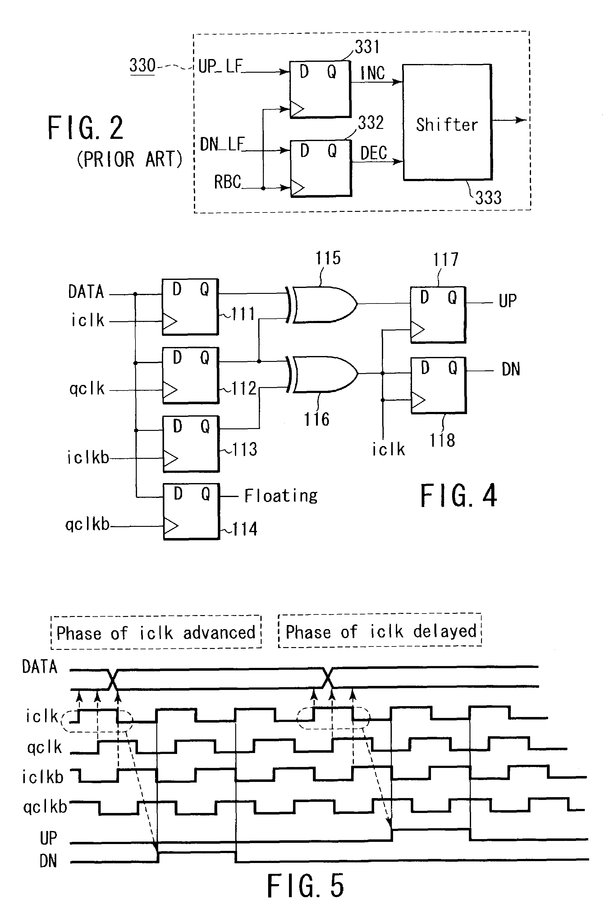
[0028]The binary type phase comparator 310 reads reception data by using four-phase sampling clocks iclk, qclk, iclkb, qclkb which are generated by the phase interpolator 340 and whose phases are shifted 90°, respectively, judges the phases of the sampling clocks relative to the reception data based on two values, i.e., an advanced value and a delayed value, and outputs judgment results in the form of a signal UP and a signal DN.
[0029]In this case, since comparing values of the reception data read by using the sampling clocks iclk, qclk, iclkb and qclkb can find sampling clock...
PUM
 Abstract
Description
Claims
Application Information