Microscope image pickup system

a pickup system and microscope technology, applied in the field of microscope image pickup system, can solve the problem that the cell of a living body has the property of being damaged

Active Publication Date: 2009-04-23
EVIDENT CORP
View PDF7 Cites 25 Cited by
  • Summary
  • Abstract
  • Description
  • Claims
  • Application Information

AI Technical Summary

Benefits of technology

[0009]In addition, the system control device can further be configured to control the operation of the capture device depending on the operation of the illumination light amount control device.
[0010]The microscope image pickup system can be configured to include a calculation device for calculating an amount of light of the illumination light in the preview mode, and the system control device controls the operation of the illumination light amount control device and the operation of the capture device depending on the amount of light calculated by the calculation device.
[0011]The microscope image pickup system can be configured to include an image quality adjustment device for adjusting the quality of the image at a plurality of stages, and the system control device controls the operation of the illumination light amount adjustment device and the operation of the capture device depending on the combination of the quality at one of a plurality of stages adjusted by the image quality adjustment device and the preview mode or the image record mode performed by the capture device.
[0012]The microscope image pickup system according to the present invention includes: a light source for emitting illumination light irradiating a test object; an object lens mounted opposite the test object; a capture device for capturing an image of the test object by the object lens; an illumination light amount control device for controlling the amount of light of the illumination light; and a system control device for controlling the operation of the capture device depending on the operation of the illumination light amount control device.
[0013]The operation of the illumination light amount control device can be adjusting the entire transmittance of one or more darkening filters provided between the test object and the light source or the intensity of the illumination light of the light source.
[0014]The operation of the capture device can be adjusting the amplification rate of the signal value indicating the image, exposure time, white balance, or black balance.

Problems solved by technology

However, a cell of a living body has the property of being damaged by the irradiation of exciting light, and gradually does no emit fluorescence in the process of the fluorescent observation.

Method used


Image

  • Microscope image pickup system
  • Microscope image pickup system
  • Microscope image pickup system

Examples


first embodiment

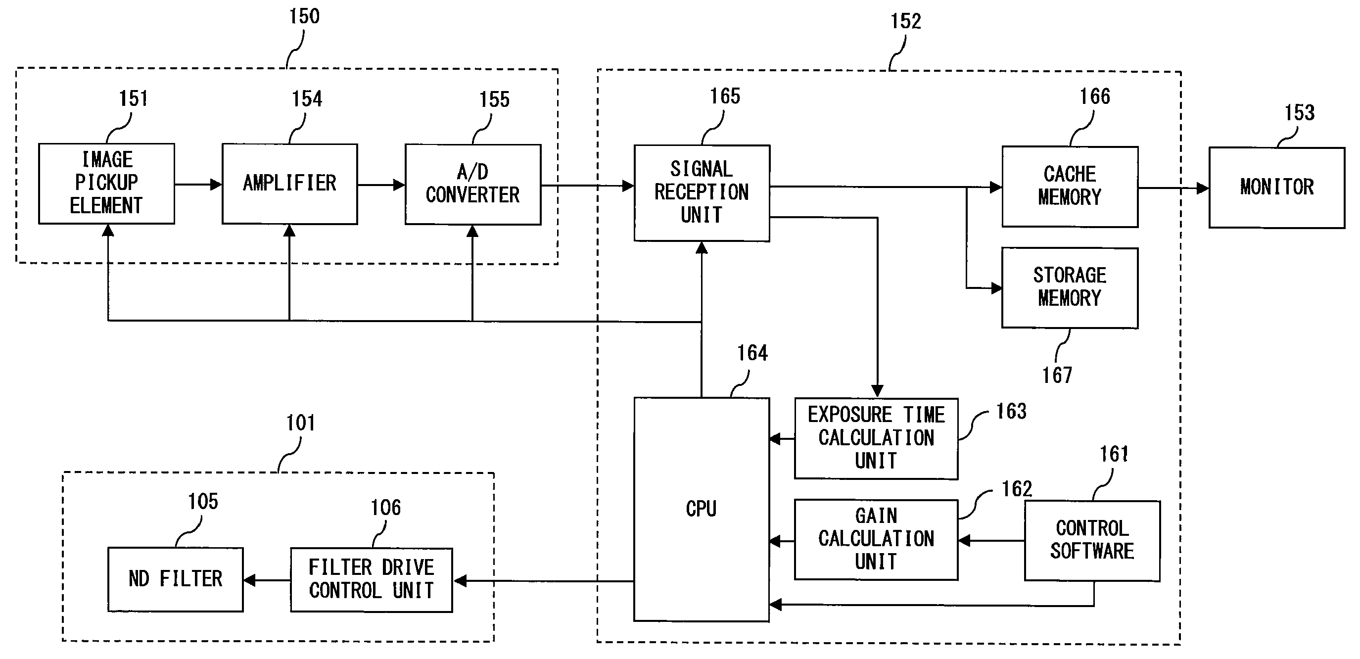
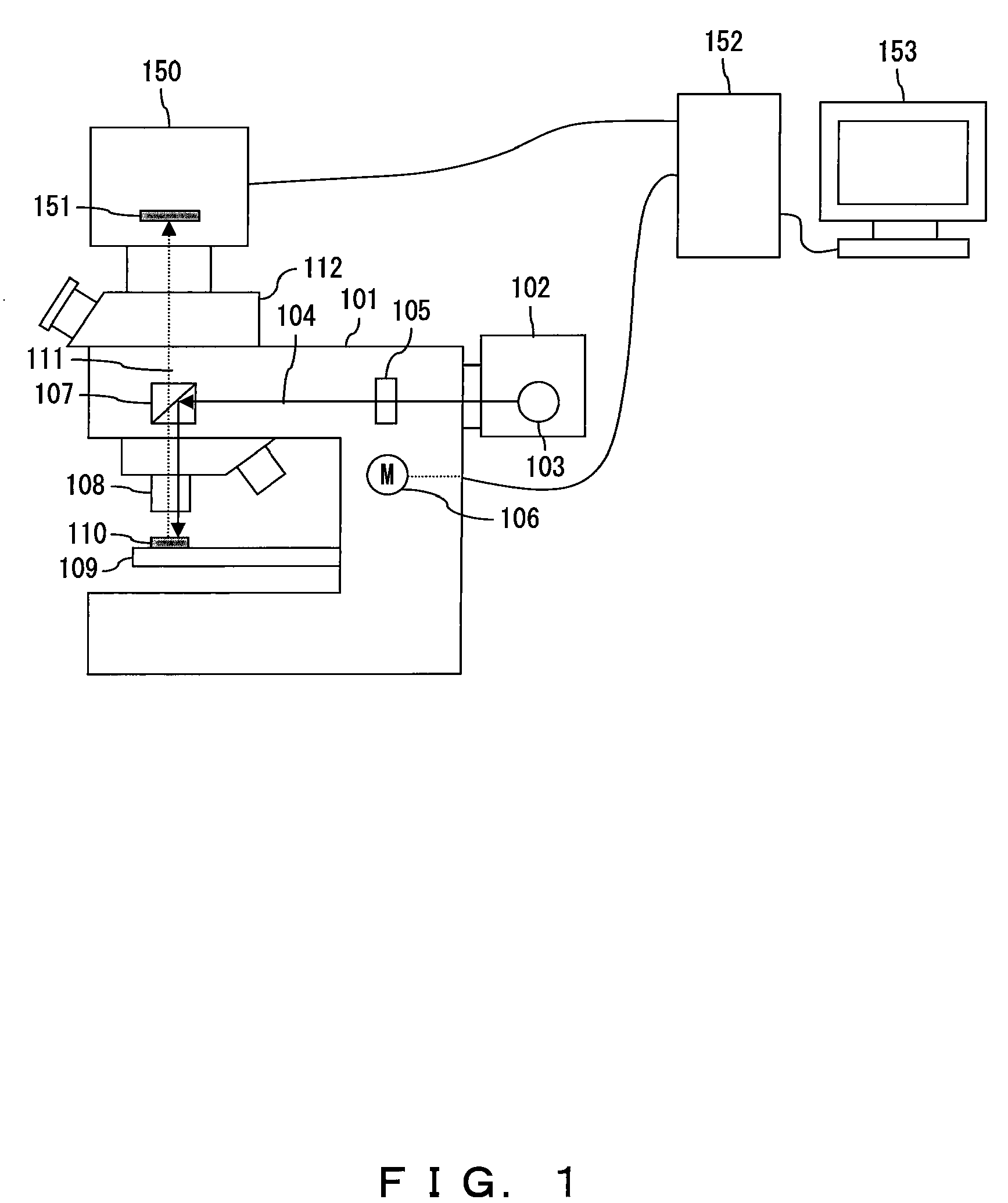
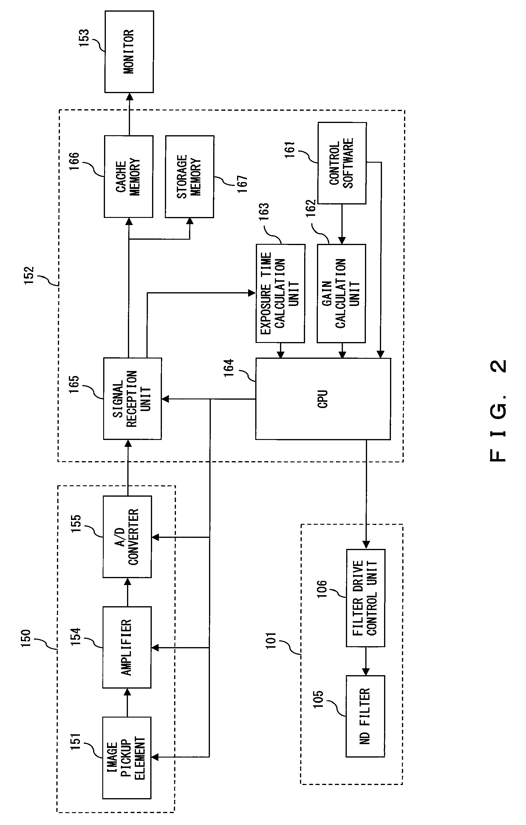
[0027]First, the configuration of the microscope image pickup system is described below with reference to FIGS. 1 and 2.

[0028]FIG. 1 or 2 shows a microscope 101, an illumination device 102 for emitting exciting light having only a specific wavelength, and a light source 103. Exciting light 104 emitted from the light source 103 in the illumination device 102 is irradiated into the inside of the microscope 101. FIGS. 1 and 2 also show a darkening filter 105 (hereinafter referred to as an ND filter), and a filter drive control unit 106. The ND filter 105 is drive controlled by the filter drive control unit 106, and is selectively inserted / removed on the optical path of the exciting light 104. FIG. 1 also shows a dichroic mirror 107. The dichroic mirror 107 is provided with a mirror for reflecting the exciting light 104 and transmitting the fluorescence 111 described later. The exciting light 104 is reflected by the dichroic mirror 107 and passes through an object lens 108, and then ir...

second embodiment

[0047]Described next is the microscope image pickup system according to the

[0048]FIG. 4 shows the internal configuration of the microscope image pickup system according to the second embodiment. FIG. 5 shows the operation condition of the filter selection unit provided for the microscope image pickup system according to the second embodiment. FIG. 6 is a flowchart for explanation of the operation of the microscope image pickup system according to the second embodiment. In FIG. 4, the same configuration as in the first embodiment is assigned the same reference numeral, and the description is omitted here.

[0049]As shown in FIG. 4, the microscope image pickup system according to the second embodiment is provided with ND filters 105a through 105c and filter drive control units 106a through 106c in the microscope 101. Additionally, the PC 152 is also provided with a signal analysis unit 201, a light quantity calculation unit 202, and a filter selection unit 203 in addition to the control...

third embodiment

[0070]Described next is the microscope image pickup system according to the present invention.

[0071]FIG. 7 shows the internal configuration of the microscope image pickup system according to the third embodiment. FIG. 8A shows the operation condition of the preview image quality setting unit provided for the microscope image pickup system according to the third embodiment. FIG. 8B shows the operation condition of the image record quality setting unit provided for the microscope image pickup system according to the third embodiment. In FIG. 7, the same configuration as in the first or second embodiment is assigned the same reference numeral, and the description is omitted.

[0072]As shown in FIG. 7, the microscope image pickup system according to the third embodiment has the PC 152 further provided with a preview image quality setting unit 210 and an image record quality setting unit 211 in addition to the control software 161, the gain calculation unit 162, the exposure time calculati...


PUM


Abstract

A microscope image pickup system includes: alight source; an object lens; a display device; a record device; a capture device for performing a preview mode in which an image of the test object obtained by the object lens is repeatedly captured and a plurality of captured images are continuously displayed on the display device, or an image record mode in which the image of the test object is captured and the captured image is recorded on the record device; an illumination light amount control device for controlling the amount of light of the illumination light; and a system control device for controlling an operation of the illumination light amount control device depending on the preview mode or the image record mode performed by the capture device.

Description

BACKGROUND OF THE INVENTION [0001]1. Field of the Invention[0002]The present invention relates to a microscope image pickup system for use in a fluorescent observation.[0003]2. Description of the Related Art[0004]In the medical and biological fields, a fluorescent observation method is used when protein, a gene, etc. in a cell of a living body are observed by a microscope. A fluorescent observation is a method in which a cell of a living body having a fluorescence indicator is irradiated with illumination light (exciting light) having a wavelength of only a specific width so that light having a wavelength (fluorescence) longer than that of the exciting light emitted from the cell of the living body. In addition, there are various capturing methods for capturing and displaying the fluorescence emitted from a cell of a living body, and images such as still images, moving pictures, etc. captured by an electronic image pickup device are not recorded, but preview images of a sample are d...

Claims


Application Information

Patent Timeline
Patent Type & Authority Applications(United States)
IPC IPC(8): H04N7/18G02B21/06
CPCG01N21/6458G02B21/365G02B21/0096
Inventor SAKAMOTO, SHINYAAIZAKI, SHINICHIRO
Owner EVIDENT CORP
Why Eureka
Try Eureka