Data processing device and data processing method
a data processing device and data processing technology, applied in the field of data processing devices and data processing methods, can solve the problems of lowering encryption strength and above data processing devices, and achieve the effect of delicate control of power consumption of operation circuits
- Summary
- Abstract
- Description
- Claims
- Application Information
AI Technical Summary
Benefits of technology
Problems solved by technology
Method used
Image
Examples
embodiment 1
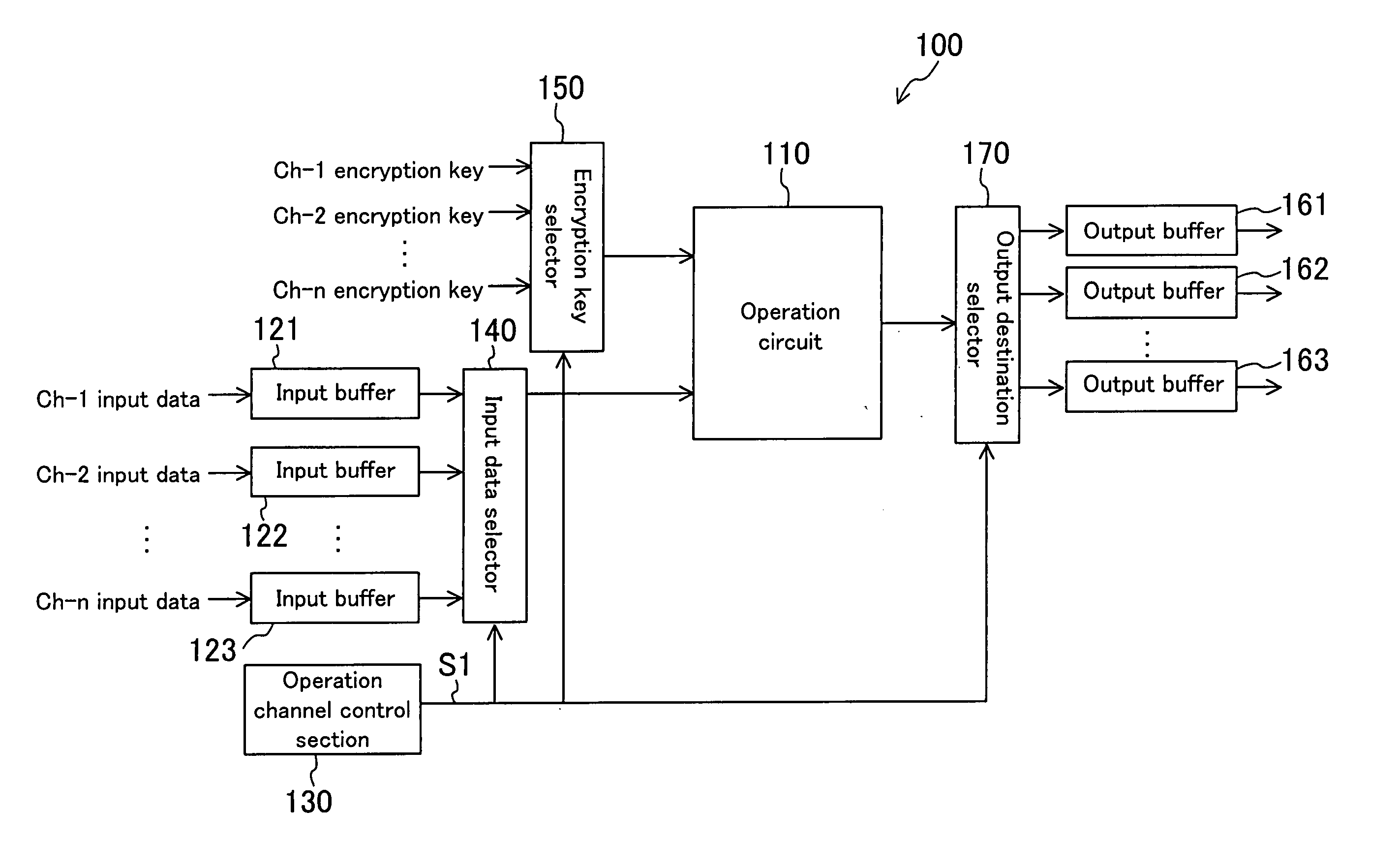
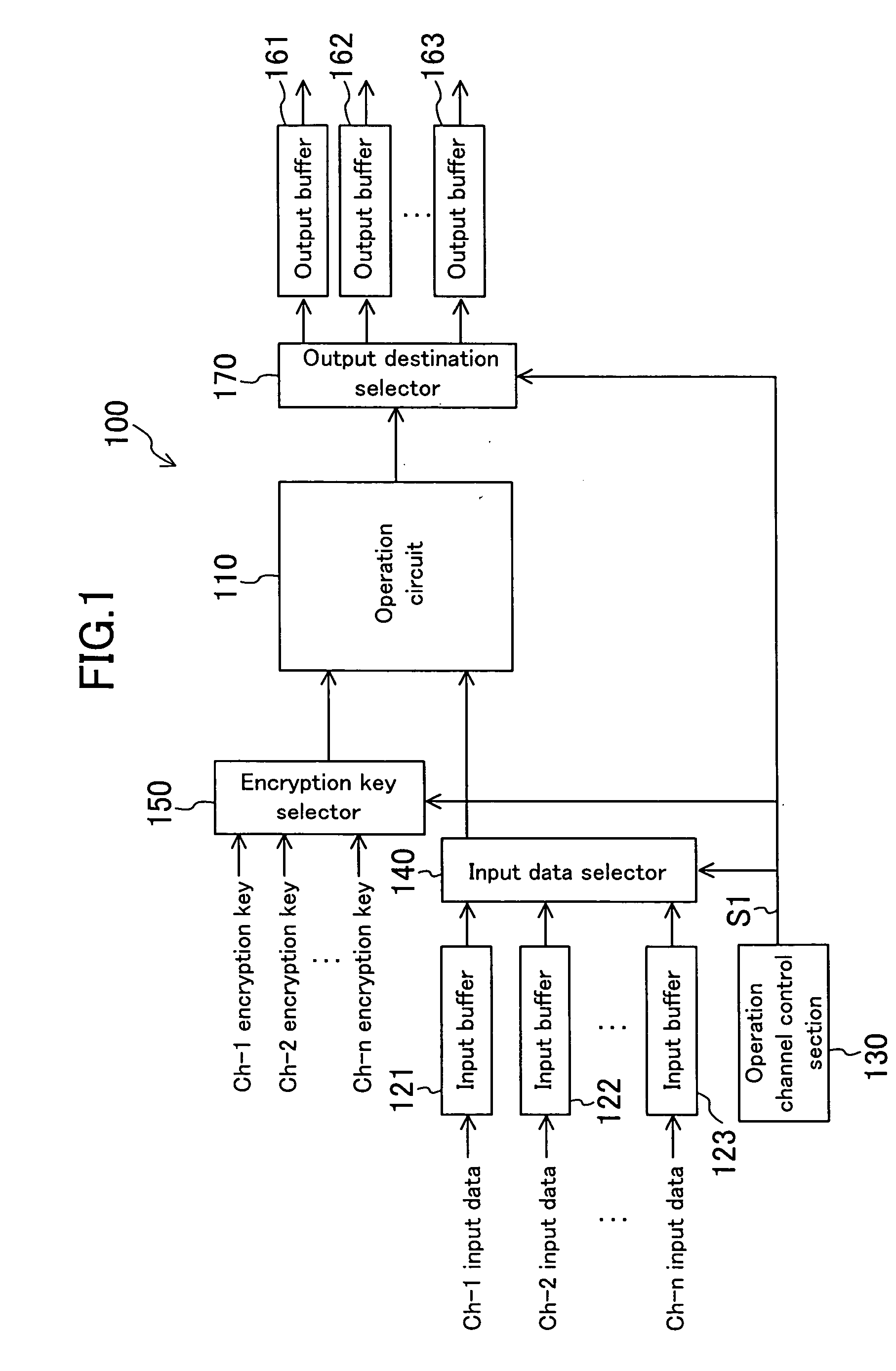
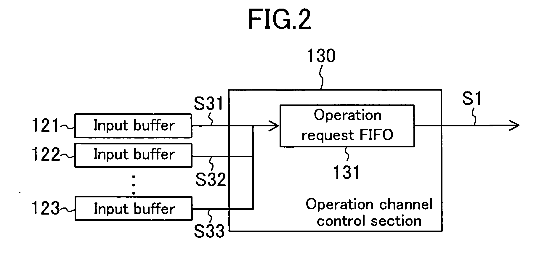
[0073]FIG. 1 is a block diagram of a data processing device 100 of Embodiment 1 of the present invention. Referring to FIG. 1, the data processing device 100 includes an operation circuit 110, input buffers 121 to 123, an operation channel control section 130, an input data selector 140, an encryption key selector 150, output buffers 161 to 163 and an output destination selector 170.
[0074] The operation circuit 110 performs operation (encryption or decryption) for data input thereinto with an encryption key supplied and outputs the operation result.
[0075] The input buffers 121 to 123, provided for respective channels (channels 1 to n), hold input data received from the corresponding channels (ch-1 input data to ch-n input data). Each of the input buffers 121 to 123 has a capacity large enough to hold data of the block unit for the encryption (or decryption) with the operation circuit 110. Once having stored data of the block unit therein, the input buffers 121 to 123 output respec...
embodiment 2
[0092]FIG. 4 is a block diagram of a data processing device 200 of Embodiment 2 of the present invention. Referring to FIG. 4, the data processing device 200 is different from the data processing device 100 in that an operation mode selector 220 is additionally provided and also an operation circuit 210 is provided in place of the operation circuit 110.
[0093] Note that in this embodiment as well as all embodiments and alterations to follow, components having substantially the same functions as those in Embodiment 1 are denoted by the same reference numerals and description of such components is omitted.
[0094] The operation circuit 210 is an operation circuit having both functions of encryption operation and decryption operation, in which operation modes (a mode for performing encryption operation and a mode for performing decryption operation) are switched to each other according to an operation mode signal S2 (to be described later) output from the operation mode selector 220. Th...
embodiment 3
[0097]FIG. 5 is a block diagram of a data processing device 300 of Embodiment 3 of the present invention. Referring to FIG. 5, the data processing device 300 is different from the data processing device 100 in that a block unit selector 320 is additionally provided and also an operation circuit 310 is provided in place of the operation circuit 110.
[0098] The operation circuit 310 is an operation circuit capable of performing encryption or decryption operation based on a plurality of types of block units (encryption key lengths). The types of block units for the operation are switched to one another according to a block unit signal S3 (to be described later) output from the block unit selector 320. The block units are defined under the block encryption schemes. For example, AES specifies block units of 128 bits, 192 bits and 256 bits.
[0099] The block unit selector 320 selects a block unit for the channel indicated by the channel information S1 output from the operation channel cont...
PUM
 Abstract
Description
Claims
Application Information
 - R&D
- Intellectual Property
- Life Sciences
- Materials
- Tech Scout
- Unparalleled Data Quality
- Higher Quality Content
- 60% Fewer Hallucinations
Browse by: Latest US Patents, China's latest patents, Technical Efficacy Thesaurus, Application Domain, Technology Topic, Popular Technical Reports.
© 2025 PatSnap. All rights reserved.Legal|Privacy policy|Modern Slavery Act Transparency Statement|Sitemap|About US| Contact US: help@patsnap.com


