Electric Door Lock

a technology of electric door locks and gear teeth, which is applied in the field of door locks, can solve the problems that the gear teeth of the first rotatable member and the gear teeth of the second rotatable member cannot be engaged during the operation of the conventional electric door lock

Inactive Publication Date: 2009-07-09
LONG CYUAN
View PDF13 Cites 25 Cited by
  • Summary
  • Abstract
  • Description
  • Claims
  • Application Information

AI Technical Summary

Problems solved by technology

The aforesaid conventional electric door lock is disadvantageous in that, since each of the gear teeth of each of the first and second rotatable members has a certain degree of thickness, when the first and second rotatable members are converted from a non-engaging to an engaging state, proper engagement between the gear teeth of the first rotatable member and the gear teeth of the second rotatable member cannot be ensured during operation of the conventional electric door lock.

Method used


Image

  • Electric Door Lock
  • Electric Door Lock
  • Electric Door Lock

Examples


Embodiment Construction

[0018]Before the present invention is described in greater detail, it should be noted that like elements are denoted by the same reference numerals throughout the disclosure.

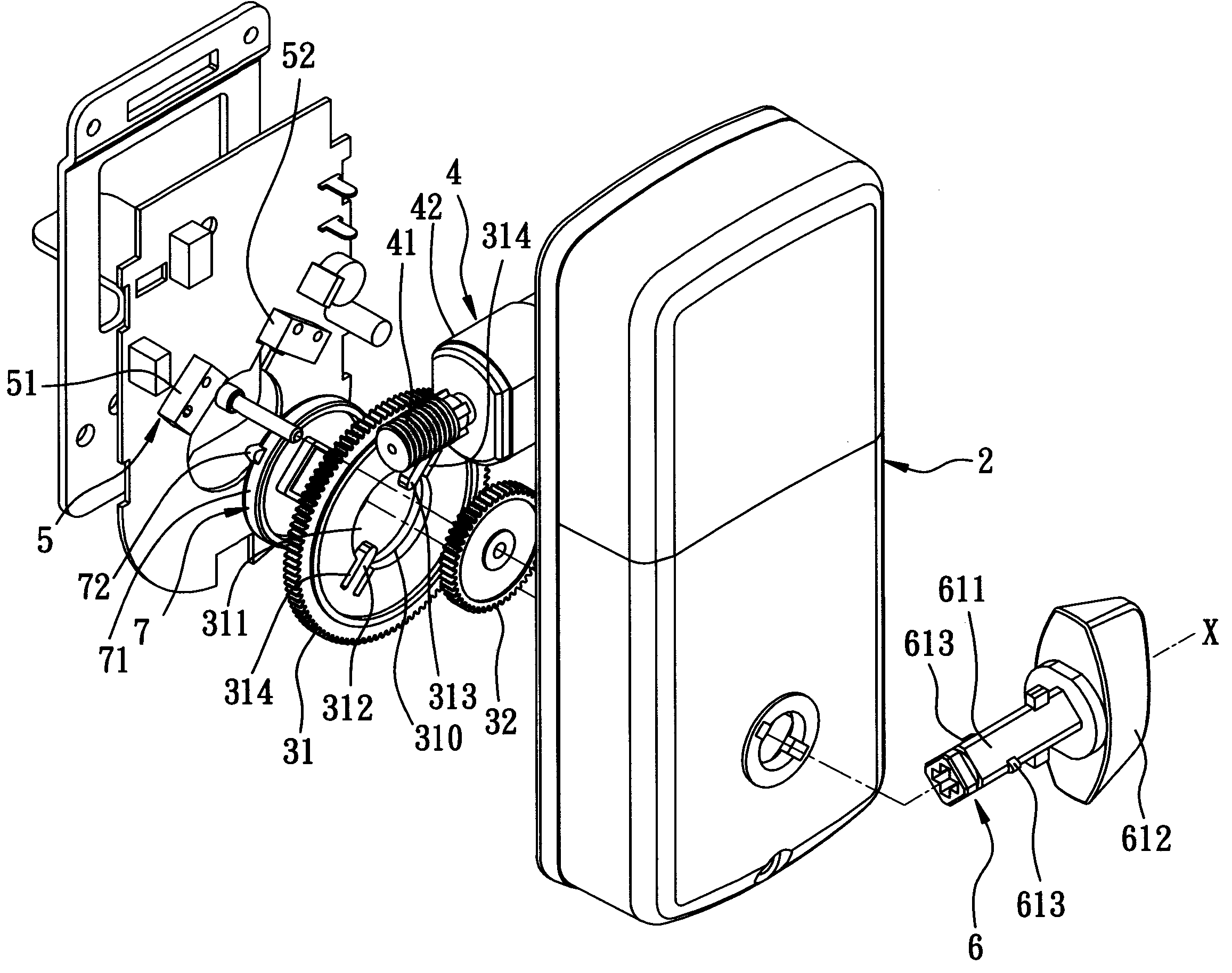
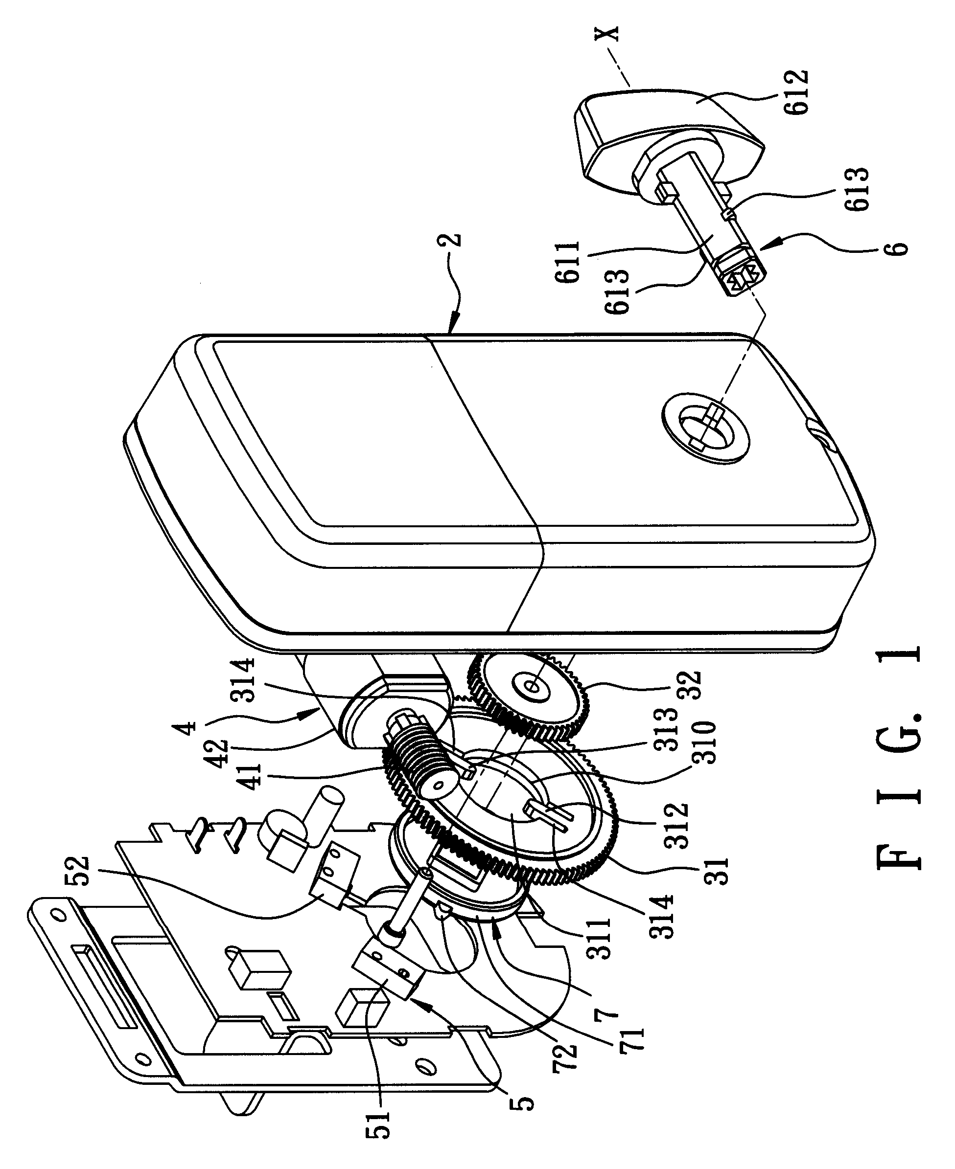
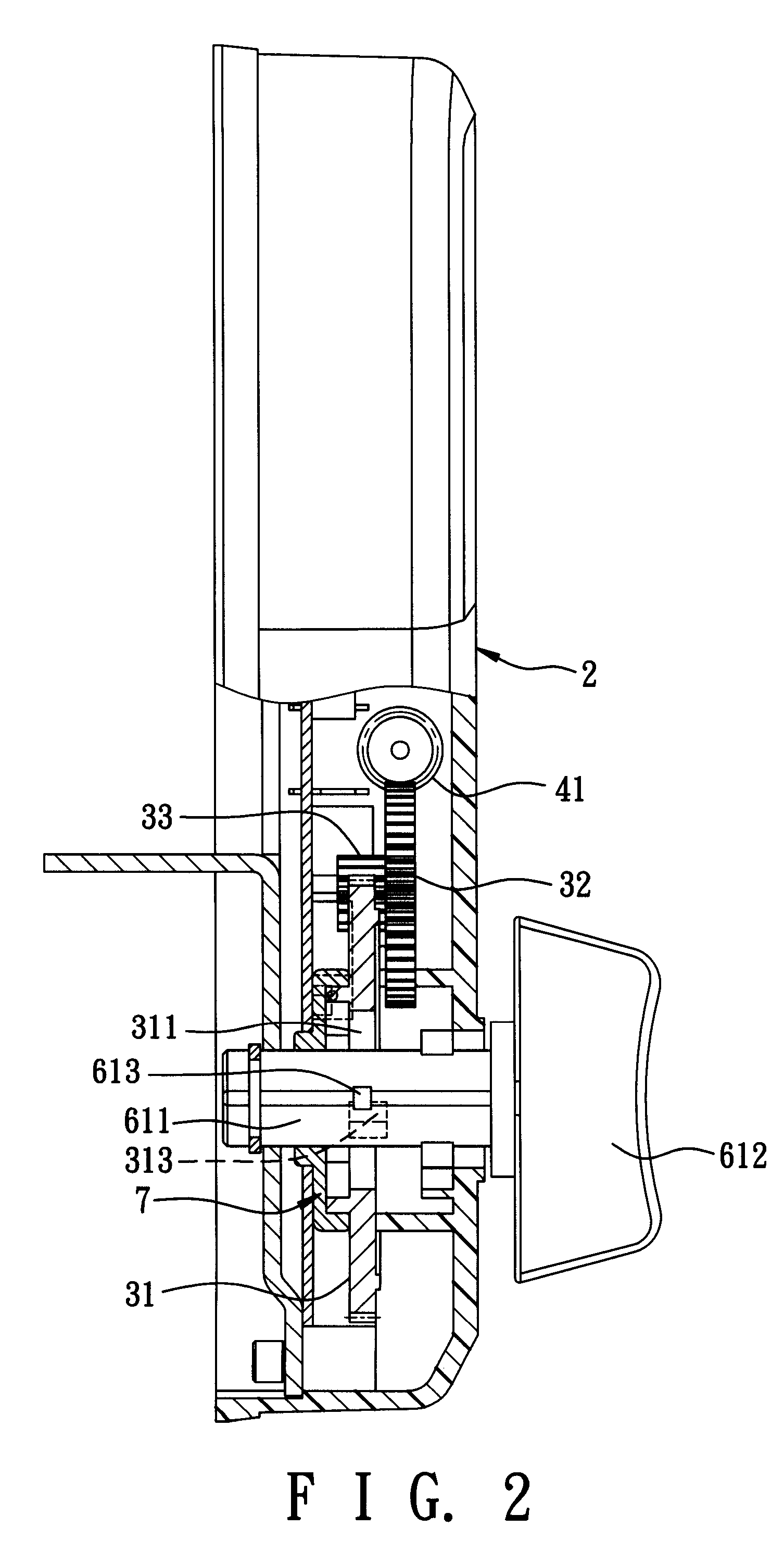
[0019]Referring to FIGS. 1 and 2, the first preferred embodiment of an electric door lock according to this invention is shown to include a lock housing 2, a rotatable member 31, a driving unit 4, and a manual operating member 6.

[0020]The lock housing 2 defines an axis (X) that extends through the manual operating member 6 when the electric door lock is assembled.

[0021]The rotatable member 31 is disposed in the lock housing 2, is rotatable relative to the lock housing 2 about the axis (X) in first and second rotational directions, is provided with a pair of diametrically opposite first protrusions 312, 313, and is formed with an axial hole 311 therethrough defined by a hole-defining wall 310. The hole-defining wall 310 of the rotatable member 31 is formed with a pair of diametrically opposite radial grooves 314....


PUM


Abstract

An electric door lock includes a rotatable member, a driving unit, and a manual operating member. The rotatable member is rotatable in first and second rotational directions and is provided with a first protrusion. The driving unit is coupled to the rotatable member, and operable so as to drive rotation of the rotatable member. The manual operating member is rotatable between locking and unlocking positions and is provided with a second protrusion. The first protrusion pushes the second protrusion to permit rotation of the manual operating member between the locking and unlocking positions when the rotatable member is driven by the driving unit to rotate in the first and second rotational directions, respectively. The second protrusion slides over the first protrusion when the manual operating member is driven to rotate between the locking and unlocking positions and when the driving unit is deactivated.

Description

BACKGROUND OF THE INVENTION[0001]1. Field of the Invention[0002]This invention relates to a door lock, more particularly to an electric door lock.[0003]2. Description of the Related Art[0004]In U.S. Patent Application Publication No. 2004 / 0245785, there is disclosed a conventional electric door lock that includes a lock housing, a manual operating member, first and second rotatable members, and a driving unit. The manual operating member extends rotatably into the lock housing, and is rotatable relative to the lock housing between locking and unlocking positions. The first rotatable member is in the form of a sector gear that has gear teeth, and is mounted rotatably in the lock housing. The second rotatable member is in the form of a gear that has gear teeth, is mounted rotatably in the lock housing, and is coupled to the manual operating member such that the second rotatable member coaxially rotates with the manual operating member between the locking and unlocking positions.[0005]...

Claims


Application Information

Patent Timeline
Patent Type & Authority Applications(United States)
IPC IPC(8): E05B47/00
CPCE05B17/0058E05B47/0012E05B2047/0025E05B2047/002E05B63/0069Y10T70/7107
Inventor LIN, LUNG-YINFAN, CHUAN-TIEN
Owner LONG CYUAN
Why Eureka
Try Eureka