Beat matching for portable audio

a portable audio and beat matching technology, applied in the field of electronic devices, can solve the problems of unnatural sounding audio outputs, limited applicability of computational complexity of scheirer, etc., and achieve the effect of avoiding harmonic jumps and minimizing time-scale modifications

Active Publication Date: 2009-07-16
TEXAS INSTR INC
View PDF6 Cites 25 Cited by
  • Summary
  • Abstract
  • Description
  • Claims
  • Application Information

AI Technical Summary

Benefits of technology

[0010]The present invention provides automatic beat matching methods which avoid harmonic jumps and / or minimize time-scale modifications with a look-back plus harmonic analysis of detected tempos.

Problems solved by technology

However, the computational complexity of Scheirer limits applicability on portable devices.
Simplistic beat matchers have problems including jumps in detected tempos over time and extreme conversion ratios that produce unnatural-sounding audio outputs.

Method used


Image

  • Beat matching for portable audio
  • Beat matching for portable audio
  • Beat matching for portable audio

Examples


first preferred embodiment beat matching

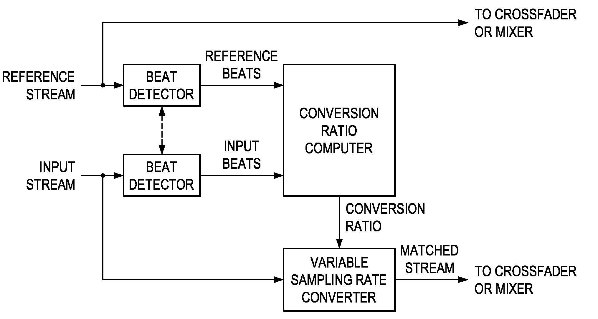
[0023]FIG. 1a illustrates functional blocks of a first preferred embodiment beat matching architecture which includes beat detectors, a conversion ratio computer, and a variable sampling rate converter; FIG. 1c is a flowchart. Sections 6 and 7 below describe a beat detector and a variable sampling rate converter, respectively.

[0024]The first preferred embodiment methods start with an initial alignment of the input digital audio stream to the reference stream by alignment of a beat detected near the beginning of the input stream with a beat detected in the reference stream, and then continue with beat-matching on a frame-by-frame basis using a variable sampling rate converter to modify the input stream to beat match the reference stream. The frames are 10-second intervals of stream samples, and adjacent frames have about a 50% overlap. Note that a 10-second interval corresponds to 441,000 samples when a stream has a 44.1 kHz sampling rate. Also, a tempo of 120 beats per minute (bpm) ...

second preferred embodiment

[0042]FIG. 3 shows a second preferred embodiment beat matching architecture which differs from that of FIG. 1a by replacement of the variable sampling rate converter with a time scale modifier (TSM). This TSM module may be used with fixed input / output buffer sizes (depending upon the conversion ratio / playback speed) and may have a playback speed resolution of 0.125. However, if the input / output buffer sizes were more flexible, this playback speed resolution could be much finer, allowing any change in playback speed with no pitch distortion artifacts. The previously described method with TSM replacing ASRC and the flowchart of FIG. 1c apply for the second preferred embodiment methods.

third preferred embodiment

[0043]FIG. 4a shows a third preferred embodiment beat matching architecture which differs from that of FIGS. 1a and 3 by replacement of the ASRC or the TSM with a combination of a TSM followed by an ASRC. The TSM performs coarse adjustments to the time scale without causing the pitch distortion which exists in sampling rate converters generally. After the TSM, the ASRC performs a much finer pitch adjustment. Note that the order of the TSM and ASRC modules could be switched while still attaining the same beat-matching functionality. Again, the flowchart FIG. 1c and (with adaptations) the previously described methods provide the third preferred embodiment methods.

[0044]In particular, a third preferred embodiment method first computes the overall conversion ratio (R[n]) necessary to align the input stream beats in the nth frame to the reference stream (or beat source) beats; next, TSM and ASRC conversion ratios (RTSM[n] and RASRC[n]) are computed as:

RTSM[n]=└R[n] / 8+1 / 16┘

RASRC[n]=R[n] / R...


PUM


Abstract

Beat matching for two audio streams extracts beats from each, computes a conversion ratio from one stream to the other stream by an initial beat alignment plus a stability-maintaining beat alignment. A variable resampling converter or time scale modifier adjusts one stream to align beats with those of the other (reference) stream. Thus for cross-fading two music streams the beats of the fading-in stream can be matched to those of the fading-out stream for a seamless transition.

Description

CROSS-REFERENCE TO RELATED APPLICATIONS[0001]This application is a division of application Ser. No. 11 / 469,745 which claims priority from U.S. provisional patent Appl. No. 60 / 713,793, filed Sep. 1, 2005. Co-assigned U.S. Pat. No. 7,345,600, issued Mar. 18, 2008, discloses related subject matter.BACKGROUND OF THE INVENTION[0002]The invention relates to electronic devices, and, more particularly, to circuitry and methods for beat matching in audio streams.[0003]In recent years, methods have been developed which can track the tempo of an audio signal and identify its musical beats. This has enabled various beat-matching applications, including beat-matched audio editing, automatic play-list generation, and beat-matched crossfades. Indeed, in a beat-matched crossfade, a deejay slows down or speeds up one of the two audio tracks so that the beats between the incoming track and the outgoing track line up. When the tracks are from the same musical genre and the beat alignment is close, the...

Claims


Application Information

Patent Timeline
Patent Type & Authority Applications(United States)
IPC IPC(8): G10H7/00
CPCG10H1/40G10H2210/076G10H2250/631G10H2250/621G10H2210/391
Inventor JOCHELSON, DANIEL S.FEDIGAN, STEPHEN J.
Owner TEXAS INSTR INC
Why Eureka
Try Eureka