
System and Method for Backlight Control for An Electronic Display

a backlight control and electronic display technology, applied in the field of electronic display technology, can solve the problems of not easily ignited, require adequate idle time to ignite, and require delicate handling, and achieve the effects of enhanced display contrast ratio, superior contrast control across the display, and flexibility in setting the luminosity of the display

Active Publication Date: 2009-07-23
POLARIS POWERLED TECH LLC
View PDF9 Cites 94 Cited by
  • Summary
  • Abstract
  • Description
  • Claims
  • Application Information

AI Technical Summary

Benefits of technology

[0010]The present invention provides novel apparatus and techniques for controlling backlighting of a display. According to one aspect of the present invention, the intensity of the backlight is adjusted multiple times within the duration of a frame. This feature provides additional flexibility in setting the luminosity of the display and also provides the ability to male a gradual transition between the luminosities of two successive frames, for example, from a bright frame to a dark frame. In another aspect of the present invention, the display is divided into a number of tiles or sections and the backlighting for each tile is separately controlled. This feature provides for superior contrast control across the display. In yet another aspect of the present invention, the backlighting can be adjusted based on ambient lighting and its effect on the perceived colors. The features of the present invention provide for an enhanced contrast ratio for the display, the removal or reduction of visual artifacts, and the flexibility to selectively emphasize and deemphasize colors based on the ambient lighting conditions.

Problems solved by technology

The display industry is enthusiastically pursuing the use of LEDs as the light source in the backlight technology because CCFLs have many shortcomings: they do not easily ignite in cold temperatures, require adequate idle time to ignite, and require delicate handling.
For example, when a very dark image immediately follows a bright image, the frame-by-frame control technique can result in undesired visual artifacts.
Similarly, for the frame in which one portion of the displayed image is bright and another portion is dark, the frame-by-frame control technique can result in undesired visual artifacts.

Method used

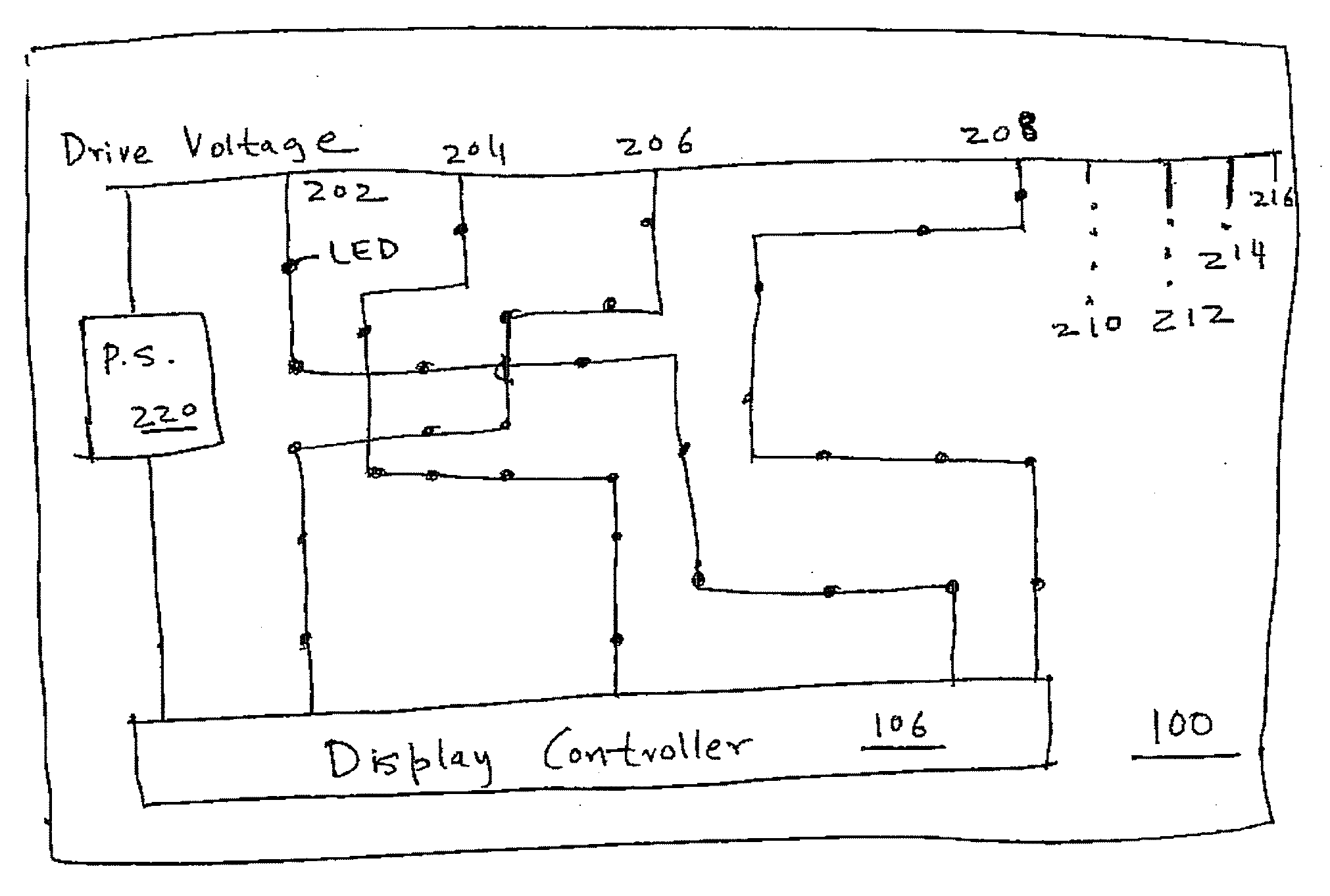

Image

  • System and Method for Backlight Control for An Electronic Display
  • System and Method for Backlight Control for An Electronic Display
  • System and Method for Backlight Control for An Electronic Display

Examples


Embodiment Construction

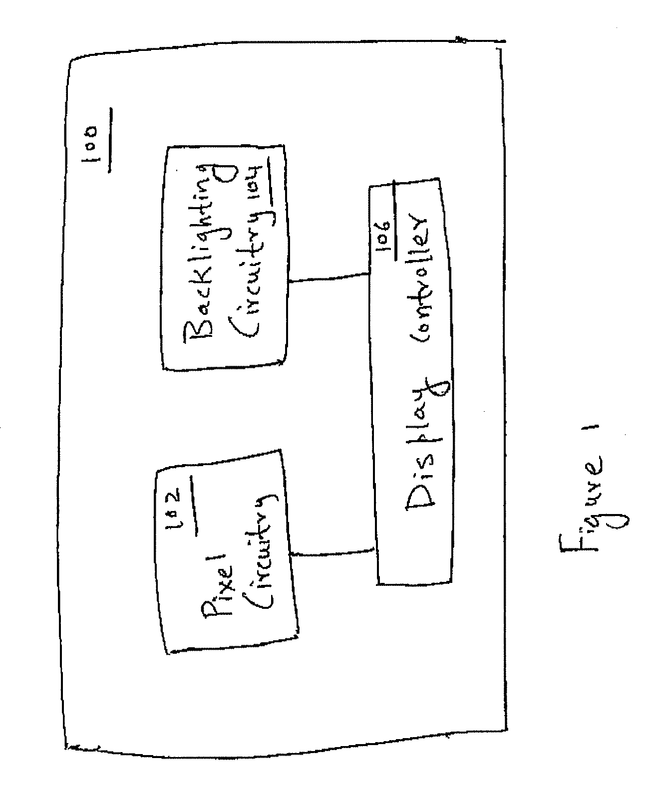
[0018]FIG. 1 illustrates a functional block diagram for a typical display, such as a liquid crystal display (LCD), in which the present invention can be implemented. The display 100 includes a pixel circuitry 102, the backlighting circuitry 104 and the display controller 106. The pixel circuitry 102 includes a large number of pixels, for example, two million pixels, arranged in a matrix of rows and columns across the display. The pixels are used for rendering the image. The pixel circuitry 102 also includes row and column drivers for selecting the pixels and providing image data to the pixels.

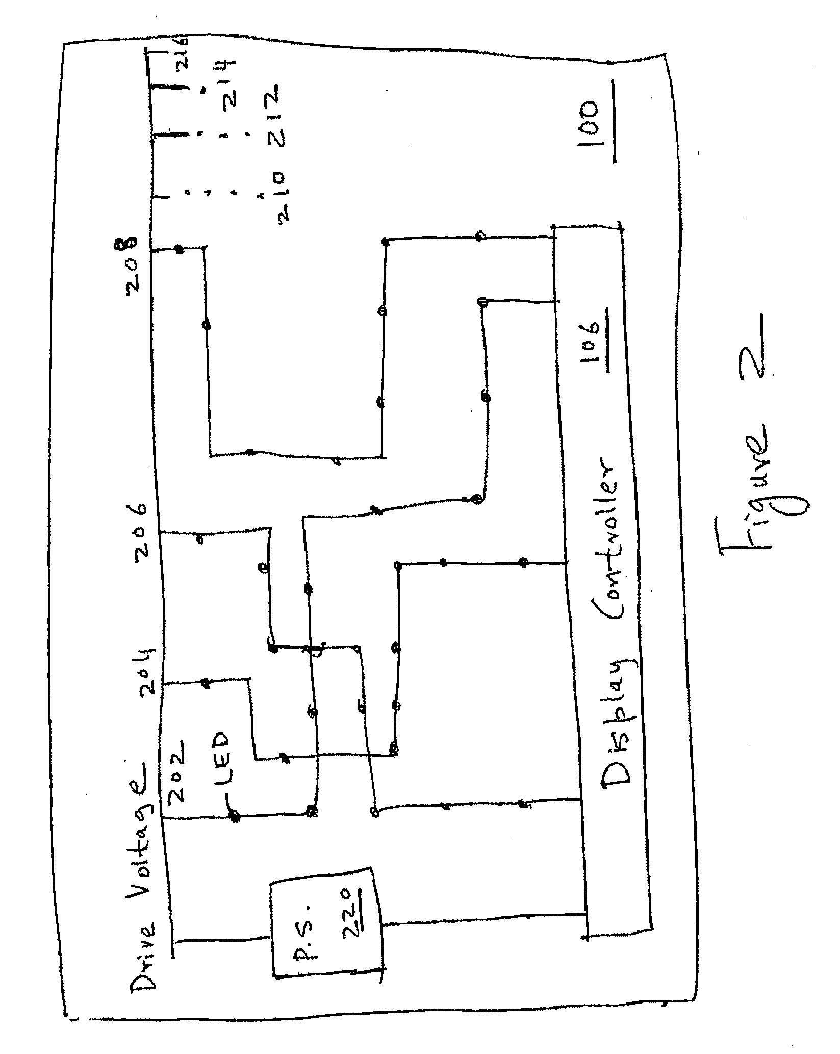
[0019]The backlighting circuitry 104 includes a number of strings of light emitting diodes (LEDS) arranged across the display 100. Typically, each string is coupled to a power supply on one end and to the ground on the other end. Preferably, each string of LEDs includes either red, blue or green LEDs. The LED strings can be selectively turned on and off for providing the various desired colors....


PUM


Abstract

The present invention discloses apparatus and techniques relating to the intelligent control of a display's backlight LED strings. The present invention provides for controlling the display intensity on a region-by-region basis and for adjusting the intensity multiple times within the duration of a frame. The present invention also provides backlight adjustment in a manner that emphasizes certain colors and deemphasizes certain colors. The present invention also provides for adjustment of the backlight based on the ambient temperature.

Description

FIELD OF INVENTION[0001]The present invention relates to electronic display technology, and particularly to controlling the intensity of light emitting diodes (LEDs) in the backlights of electronic displays.BACKGROUND OF THE INVENTION[0002]Backlights are used to illuminate thick and thin film displays including liquid crystal displays (LCDs). LCDs with backlights are used in small displays for cell phones and personal digital assistants (PDAs), as well as in large displays for computer monitors and televisions. Typically, the light source for the backlight includes one or more cold cathode fluorescent lamps (CCFLs). The light source for the backlight can also be an incandescent light bulb, an electroluminescent panel (ELP), or one or more hot cathode fluorescent lamps (HCFLs).[0003]The display industry is enthusiastically pursuing the use of LEDs as the light source in the backlight technology because CCFLs have many shortcomings: they do not easily ignite in cold temperatures, requ...

Claims


Application Information

Patent Timeline
IPC IPC(8): G09G3/32
CPCG09G3/3413G09G3/3426G09G2310/0237G09G2360/144G09G2320/0633G09G2320/0666G09G2310/024
Inventor S., DILIPSANTO, HENDRIKDHAYAGUDE, TUSHARVI, KLENCHEN, SEAN
Owner POLARIS POWERLED TECH LLC
Learn More