Land Clearing Rake

a technology for clearing rakes and rakes, which is applied in the field of attachments for earth moving equipment, can solve the problems of limited use of bulldozers, unplanned equipment downtime, and often economic impracticality of practi

Inactive Publication Date: 2009-07-30
PARRISH MARLIN
View PDF19 Cites 24 Cited by
  • Summary
  • Abstract
  • Description
  • Claims
  • Application Information

AI Technical Summary

Problems solved by technology

Bulldozer moldboards with integral teeth tend to limit the use of the bulldozer to either a raking mode or a grading mode.
The time to perform this somewhat cumbersome task is usually significant and results in unwanted down time for the equipment.
Separate bulldozers could be used to avoid changeover time, but this practice is often economically impractical.
Another disadvantage of this approach is that the additional moldboard to be used must be moved from one work site to the next.
In some cases, the time and effort required to transition between the deployed and undeployed positions is significant.
In other cases, the time and effort required to transition between the deployed and undeployed positions may be reduced, but the assembly may not always provide a method to place the teeth in a position that minimizes interference with the use of the moldboard.

Method used


Image

  • Land Clearing Rake
  • Land Clearing Rake
  • Land Clearing Rake

Examples


Embodiment Construction

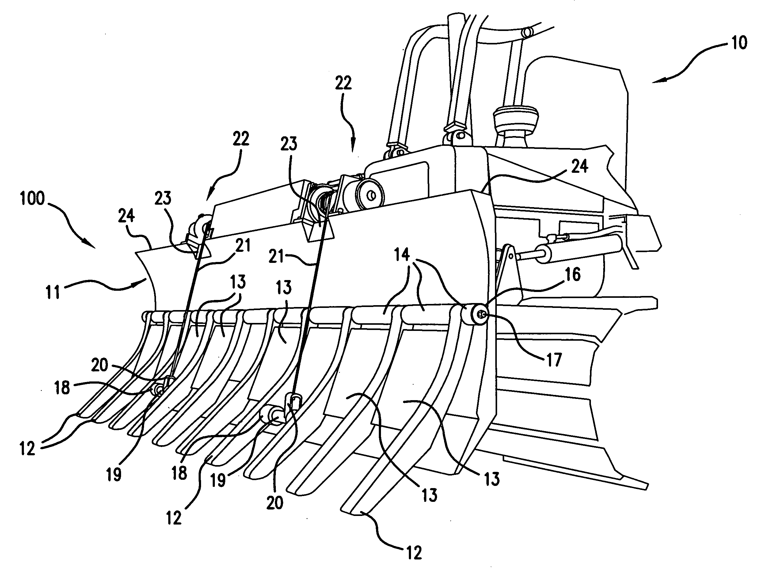
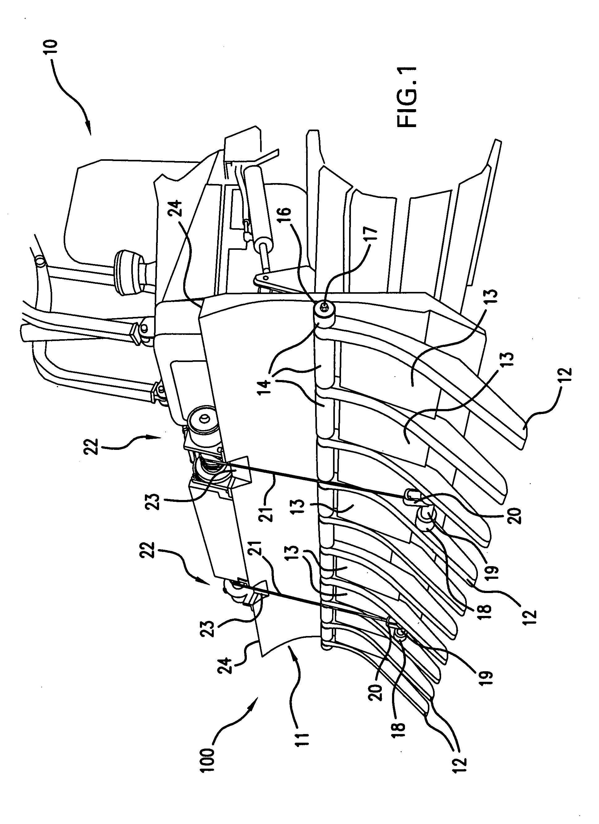
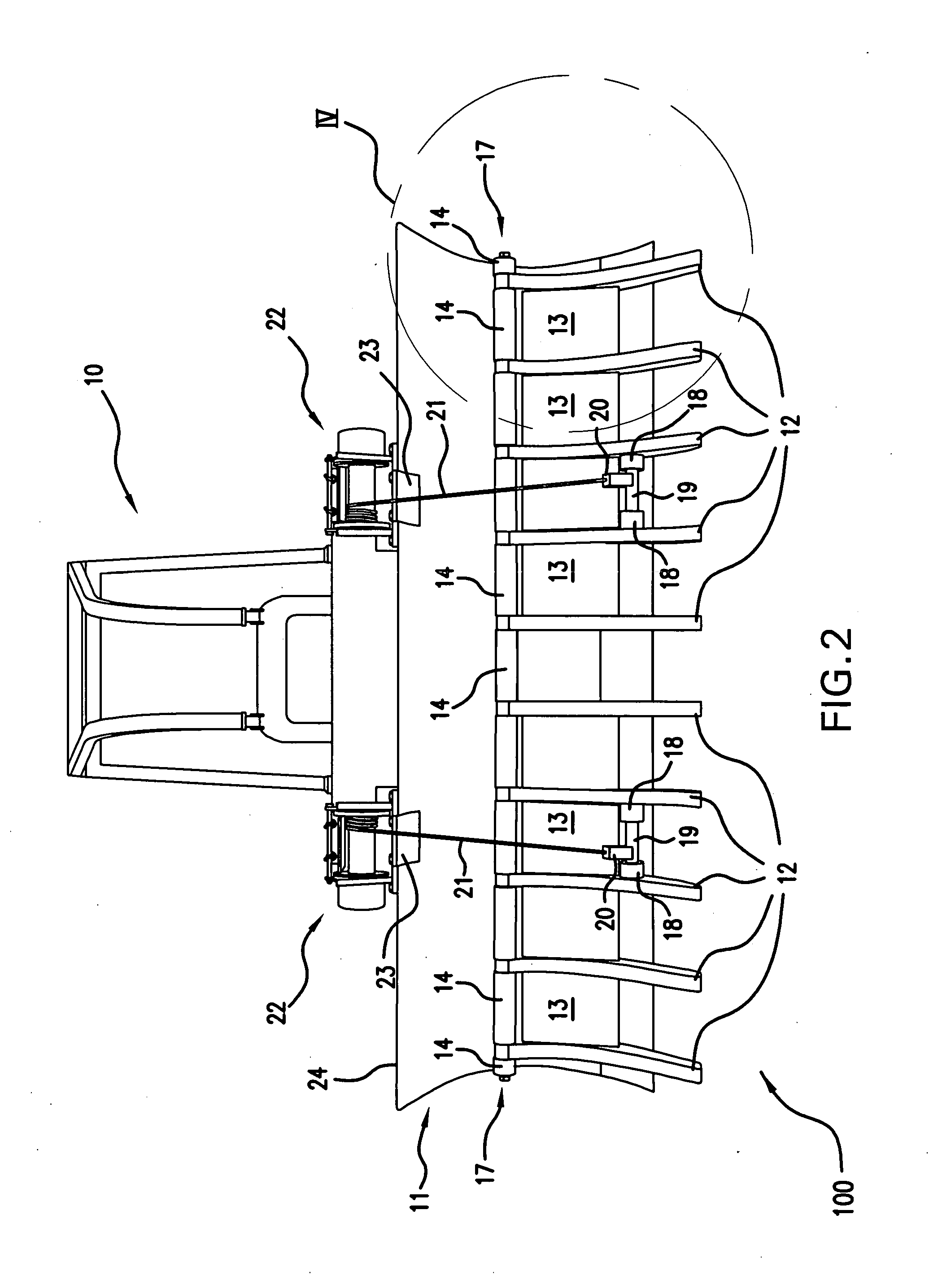
[0012]According to the embodiments described herein, a land clearing rake is disclosed. The land clearing rake includes a set of heavy-duty teeth that are specifically contoured for efficient raking of roots and other land clearing debris when the rake is in the deployed position. The rake teeth pivot about a shaft that is horizontally connected to the front of the dozer moldboard, or blade, near the midpoint of the dozer moldboard. The land clearing rake teeth are connected to each other by means of heavy-duty plates between each of the teeth.

[0013]The disclosed land clearing rake may attain many configurations. In one embodiment, the invention involves two sections of teeth and plates. In this embodiment, the two teeth near the center of the dozer moldboard are not connected to each other by plates. The sections are hinged at the center-point on the front of the moldboard and can be simultaneously raised and lowered by means of two winches. The winches may be electric, hydraulic, ...


PUM


Abstract

The invention is a land clearing rake that is typically mounted on a moldboard on a conventional bulldozer. The land clearing rake pivots about a shaft that is horizontally connected to the front of the moldboard. The rake is comprised of teeth connected to each other by heavy-duty plates between each of the teeth. The teeth may be arranged in one or more sections wherein the sections can be simultaneously raised or lowered by winches mounted on the moldboard. The winches are remotely controlled from the operator's seat. Thus, the land clearing rake is capable of being quickly raised or lowered by the operator while the earth moving equipment is moving back to prepare for another forward move. The ability to quickly transition between raking and grading modes significantly improves the efficiency of land clearing operations.

Description

CROSS-REFERENCE TO RELATED APPLICATION[0001]This application is a continuation-in-part of application Ser. No. 11 / 333,490 filed Jan. 17, 2006.FIELD OF THE INVENTION[0002]This invention relates to attachments for earth moving equipment, such as bulldozers, front-end loaders, skidders, graders, and the like. More particularly, this invention relates to a set of raking teeth that are pivotally secured to a moldboard used on heavy equipment, such as a bulldozer or other earth moving equipment.BACKGROUND OF THE INVENTION[0003]Bulldozers with planar moldboards, or blades, mounted on the front are commonly used in a variety of land clearing applications including raking and grading. In raking applications, roots, limbs, and other undesirable debris are removed from an area. For grading applications, the lower edge of the moldboard is scraped along a surface in order to smooth or level the land. In order to perform the raking operation, bulldozers sometimes rely upon attachments with protru...

Claims


Application Information

Patent Timeline
Patent Type & Authority Applications(United States)
IPC IPC(8): A01B31/00A01B23/02E02F3/815
CPCE02F1/00F41H11/28F41H11/24E02F3/8152A01G23/006
Inventor PARRISH, MARLIN
Owner PARRISH MARLIN
Why Eureka
Try Eureka