Encapsulated pole unit conductor assembly for an encapsulated pole unit and medium voltage circuit interrupter including the same

a technology of encapsulated poles and conductor assemblies, which is applied in the direction of air-break switches, high-tension/heavy-dress switches, electrical apparatus, etc., can solve the problems of corresponding circuit breakers being relatively large and relatively heavy, and cts that are likely to fail during circuit breaker testing

Active Publication Date: 2009-08-13
EATON INTELLIGENT POWER LTD
View PDF4 Cites 28 Cited by
  • Summary
  • Abstract
  • Description
  • Claims
  • Application Information

AI Technical Summary

Problems solved by technology

However, such known bottom conductors do not include any current transformer (CT) or any electronic sensing circuit.
Since known CTs for corresponding circuit breakers are relatively very large and relatively very heavy, they are not disposed at the circuit breaker.
Furthermore, such CTs would likely fail during circuit breaker testing.

Method used


Image

  • Encapsulated pole unit conductor assembly for an encapsulated pole unit and medium voltage circuit interrupter including the same
  • Encapsulated pole unit conductor assembly for an encapsulated pole unit and medium voltage circuit interrupter including the same
  • Encapsulated pole unit conductor assembly for an encapsulated pole unit and medium voltage circuit interrupter including the same

Examples


Embodiment Construction

[0026]Directional phrases used herein, such as, for example, left, right, upper, lower, above, below, clockwise, counterclockwise and derivatives thereof, relate to the orientation of the elements shown in the drawings and are not limiting upon the claims unless expressly recited therein.

[0027]As employed herein, the term “fastener” refers to any suitable connecting, tightening or fastening mechanism expressly including, but not limited to, screws, bolts and the combinations of bolts and nuts (e.g., without limitation, lock nuts) and bolts, washers and nuts.

[0028]As employed herein, the statement that two or more parts are “coupled” together means that the parts are joined together either directly or joined through one or more intermediate parts.

[0029]As employed herein, the term “number” means one or an integer greater than one (i.e., a plurality).

[0030]As employed herein, the term “encapsulated” means at least substantially surrounded by a number of insulative structures.

[0031]As ...


PUM


Abstract

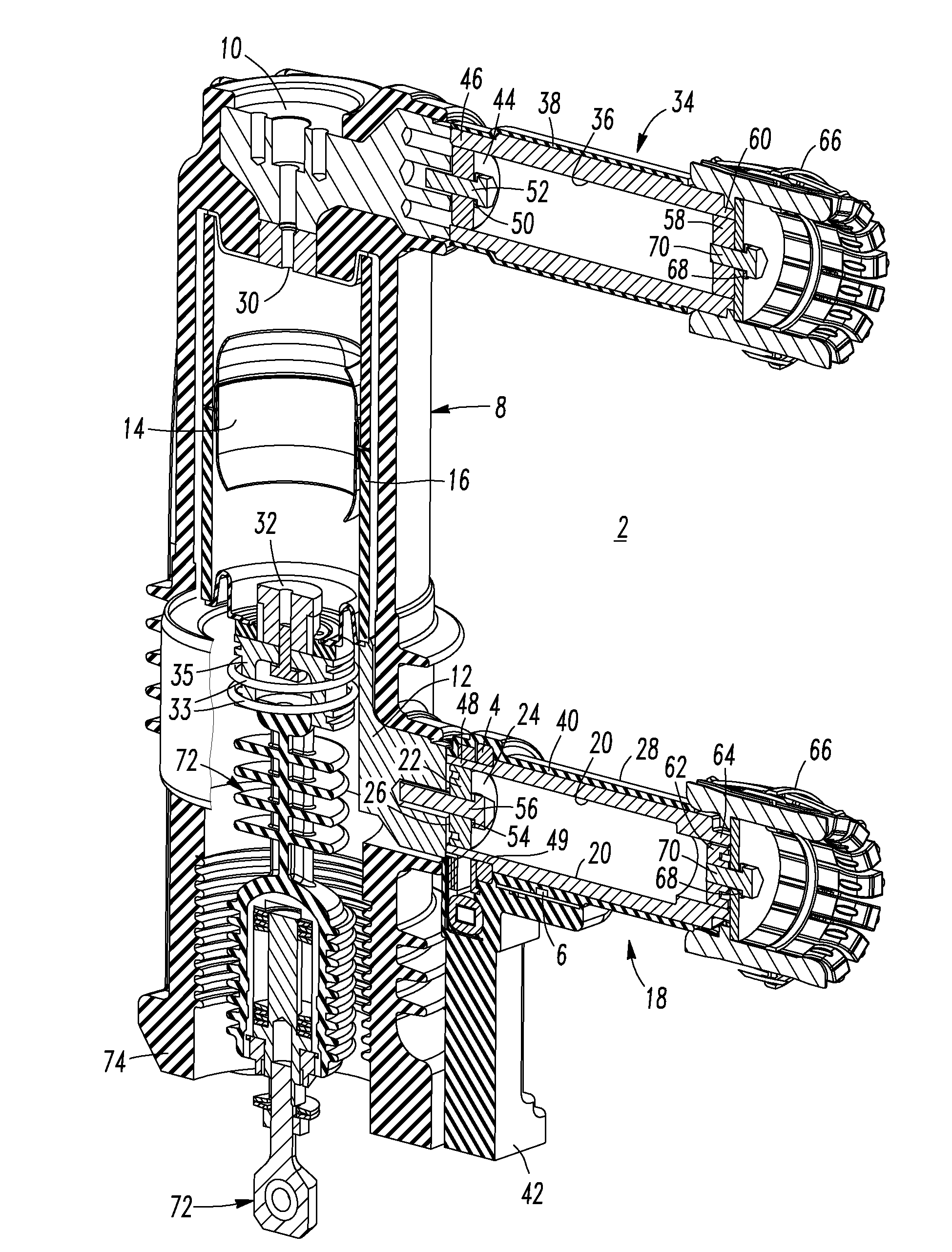
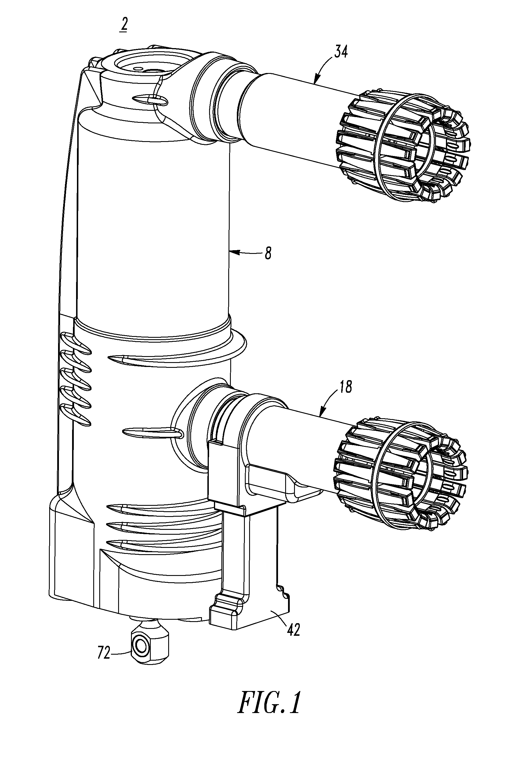
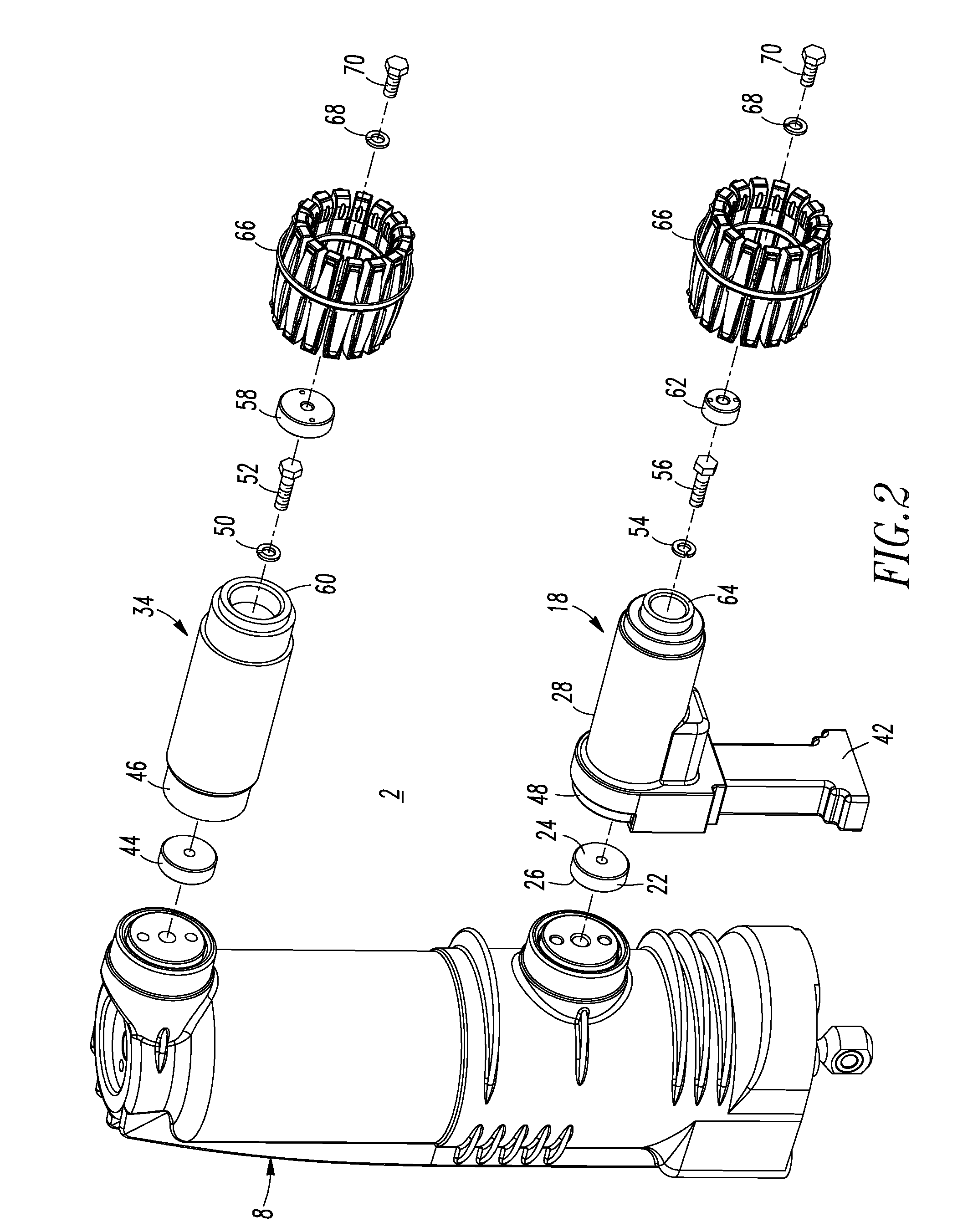
A medium voltage circuit interrupter includes a circuit interrupter housing and a plurality of poles. Each of the poles includes an encapsulated pole unit. The encapsulated pole unit includes a first unit having a first conductor, a second conductor, a vacuum interrupter electrically connected between the first conductor and the second conductor, and a first housing housing the vacuum interrupter. A removable second unit includes a third conductor, a fourth conductor having a first portion electrically connected to the third conductor and a second portion removably electrically connected to one of the first conductor and the second conductor, an electronic device structured to sense a characteristic of the pole, and a second insulative housing encapsulating the third conductor, the first portion of the fourth conductor and the electronic device. An operating mechanism is structured to open and close the vacuum interrupter of each of the poles.

Description

BACKGROUND OF THE INVENTION[0001]1. Field of the Invention[0002]This invention pertains generally to circuit interrupters and, more particularly, to medium voltage circuit breakers including a plurality of poles. The invention also relates to pole units for circuit interrupters. The invention further relates to pole unit conductor assemblies for pole units.[0003]2. Background Information[0004]Circuit interrupters provide protection for electrical systems from electrical fault conditions such as, for example, current overloads and short circuits. Various circuit interrupters include a spring powered operating mechanism, which opens electrical contacts to interrupt the current through the conductors of an electrical system in response to abnormal conditions, although a wide range of mechanical, electromechanical or other suitable driving mechanisms may be employed.[0005]Vacuum circuit interrupters (e.g., vacuum circuit breakers; vacuum reclosers; other vacuum switching devices) includ...

Claims


Application Information

Patent Timeline
Patent Type & Authority Applications(United States)
IPC IPC(8): H01H33/66
CPCH01H33/6606H01H33/59
Inventor CHEN, STEVEN Z.BENKE, JAMES J.JENKINS, ZACHARY R.ZHOU, XIN
Owner EATON INTELLIGENT POWER LTD
Why Eureka
Try Eureka