Vpls n-pe redundancy using pseudo wire fast failover

Active Publication Date: 2009-08-13
CISCO TECH INC
View PDF4 Cites 48 Cited by
  • Summary
  • Abstract
  • Description
  • Claims
  • Application Information

AI Technical Summary

Problems solved by technology

Further, the method includes disabling the active PW when a failure of the active PW is detected.

Method used


Image

  • Vpls n-pe redundancy using pseudo wire fast failover
  • Vpls n-pe redundancy using pseudo wire fast failover
  • Vpls n-pe redundancy using pseudo wire fast failover

Examples


example embodiments

Description of Example Embodiments

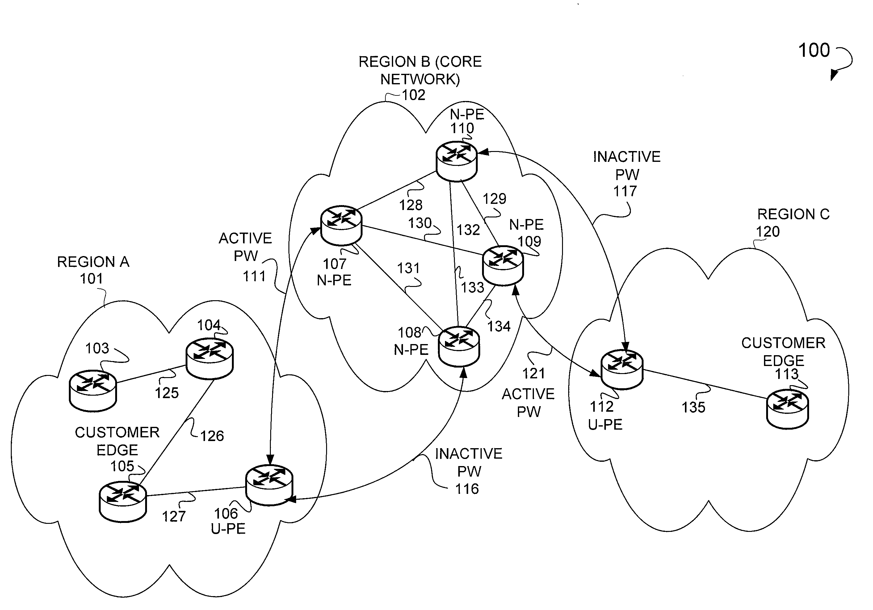
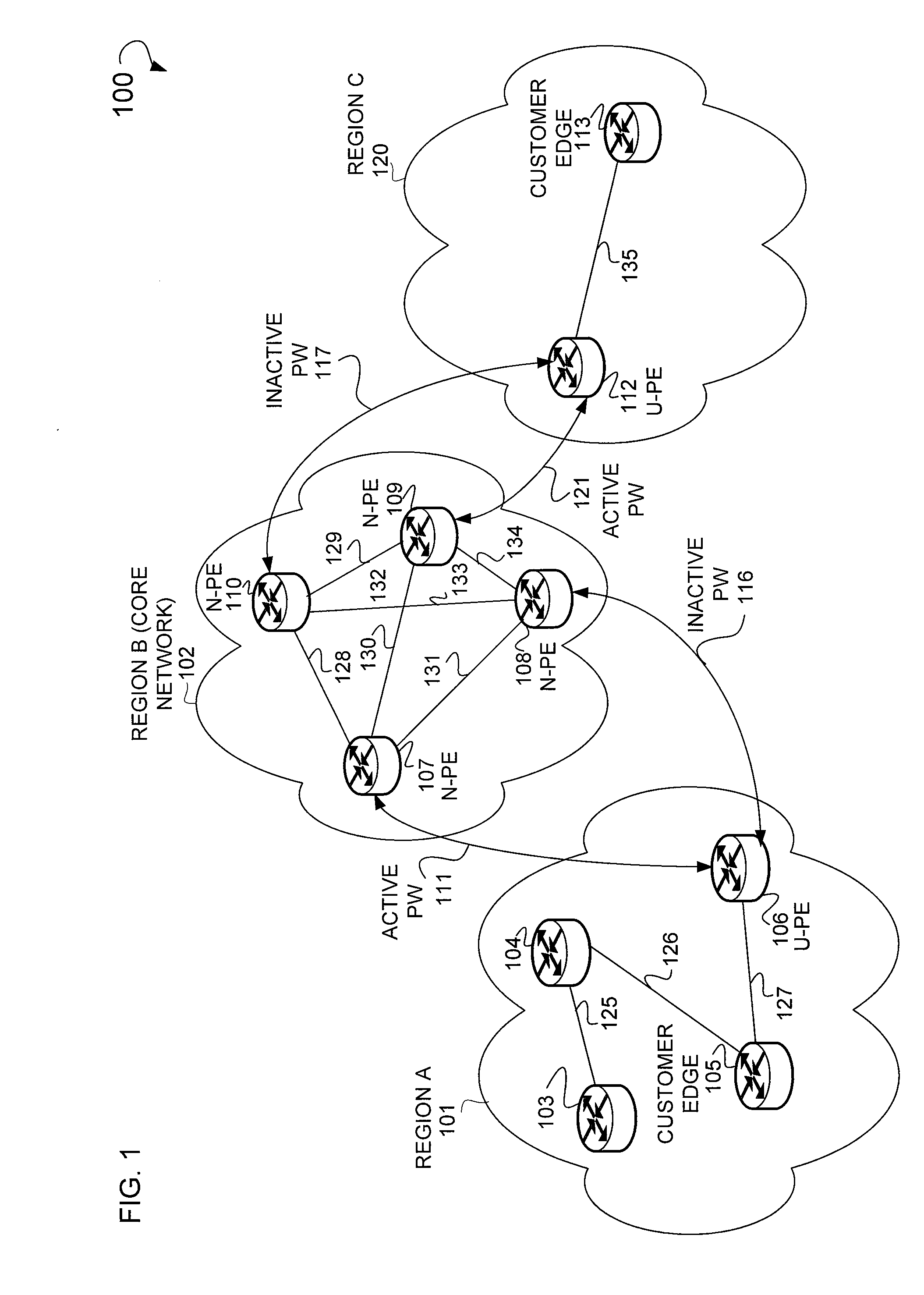
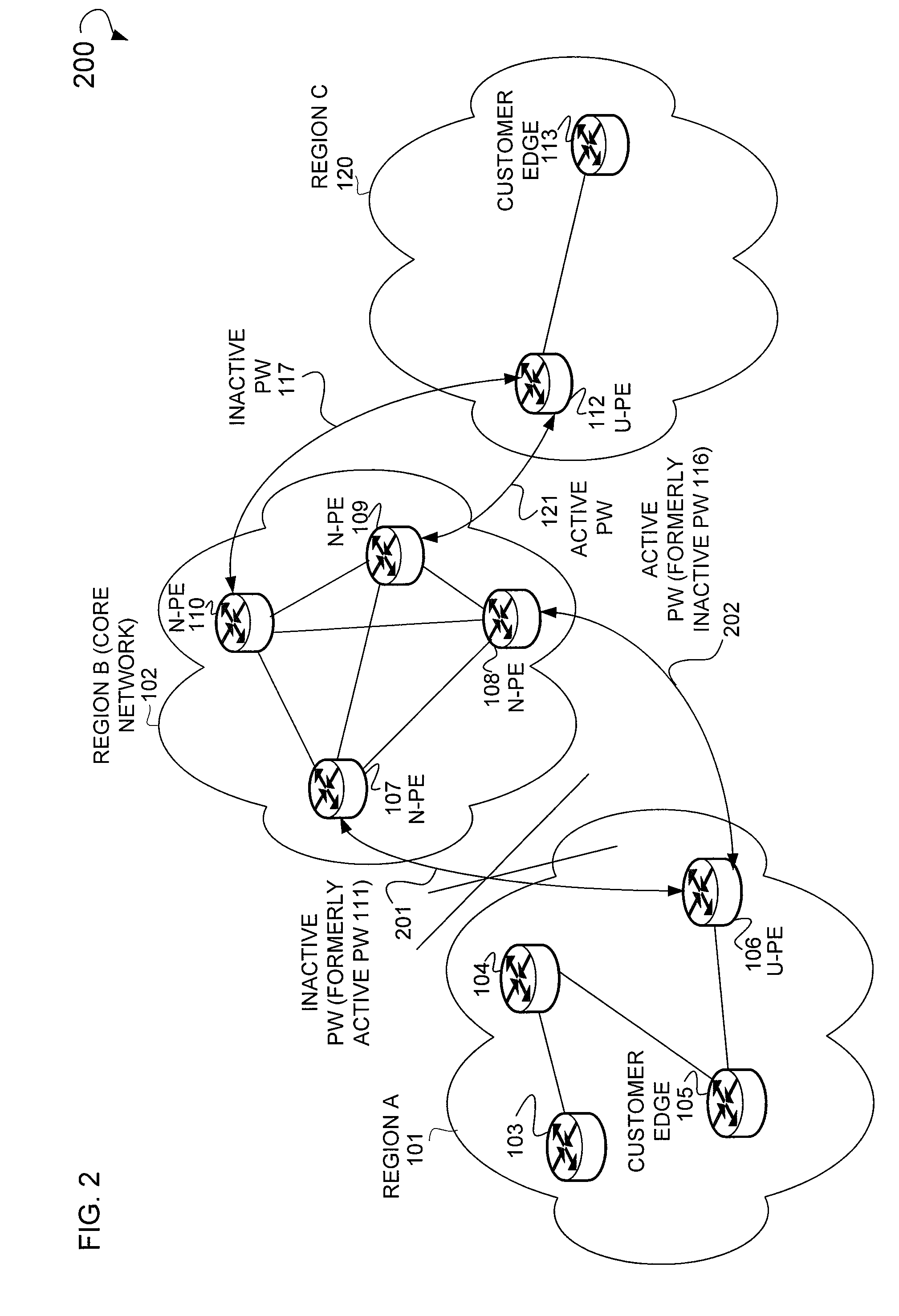
[0023]In some example embodiments, an apparatus and method for PW fast failover are shown. This apparatus may be a network appliance, and the method a computer implemented method. Further, the computer implemented method and network appliance illustrated herein may be implemented on a U-PE, N-PE, or plurality or U-PEs and N-PEs.

[0024]In some example embodiments, as illustrated herein, a VPLS-domain Layer-2 (L2) network within the Hierarchical-VPLS (H-VPLS) network between the U-PE and N-PE is shown as inherently loop-free. The term “between,” as used herein may include various physically or logically defined paths that may or may not include other network appliances. Additionally, the term “between” may denote a bi-directional flow. This loop-free nature is ensured by having a single active L2-connection per-VPLS domain (e.g., a single active PW) between the VPLS-bridges at the U-PE and N-PE. Moreover, the VPLS-domain illustrated herein may have mor...


PUM


Abstract

In one example embodiment, a system and method is provided that includes establishing a plurality of Pseudo Wire (PW) connections between a first network appliance region and a second network appliance region to transmit data from the first network appliance region to the second network appliance region along an active PW. Further, the method includes disabling the active PW when a failure of the active PW is detected. Additionally, the method may include selecting an inactive PW to become a new active PW such that the data may be transmitted from the first network appliance region to the second network appliance region. Moreover, the method includes switching from the active PW to the new active PW.

Description

FIELD[0001]This application relates to a system and method for utilizing connections among network appliances.BACKGROUND[0002]Systems and methods implemented in a Virtual Private Local Area Network Service (VPLS) environment may utilize Pseudo Wire (PW) connections among one or more network appliances (e.g., a router, switch, bridge or other suitable device, collectively referenced as apparatus) to transmit data among these network appliances. A PW may be logical connection between two or more network appliances. Further, a PW may be an emulation of a native service over a Packet Switched Network (PSN). A PSN may be an Internet Protocol (IP) based network, X.25 based network, frame relay, Asynchronous Transfer Mode (ATM), or some other suitable network. In terms of network architecture, these PW connections may connect two or more network appliances in the form of Provider Edge (PE) appliances. These PEs appliances may be connected to one or more network appliances in the form of Cu...

Claims


Application Information

Patent Timeline
Patent Type & Authority Applications(United States)
IPC IPC(8): H04L12/28
CPCH04L45/04H04L45/22H04L43/0811H04L45/68H04L45/28
Inventor KUMAR, RAKESHSHAH, JAYCHEN, JASON XIAOGUANG
Owner CISCO TECH INC
Why Eureka
Try Eureka