Cyclone dust-collecting apparatus for vacuum cleaner

a vacuum cleaner and dust collection technology, applied in the direction of cleaning filter means, auxillary pretreatment, separation processes, etc., to achieve the effect of greater dust collection capacity

Inactive Publication Date: 2009-08-20
SAMSUNG GWANGJU ELECTRONICS CO LTD
View PDF20 Cites 13 Cited by
  • Summary
  • Abstract
  • Description
  • Claims
  • Application Information

AI Technical Summary

Benefits of technology

[0023]According to the present disclosure, dust not settle on top surfaces of the components, such as the inflow pipe or extension pipe, disposed inside the body of the cyclone dust-collecting apparatus, and falls into the lower portion of the body, so that it is possible to prevent dust from remaining inside the body and to empty the body once.
[0024]Additionally, according to the present disclosure, the cyclone unit partially protrudes from the body, so it is possible to have greater dust-collecting capacity while maintaining a compact size.

Problems solved by technology

Unfortunately, current cyclone dust-collecting apparatuses allow dust to settle on components inside the apparatus.
Further, current cyclone dust-collecting apparatuses have proven difficult to empty and, thus, allow dust to remain inside the body when the cyclone dust-collecting apparatus is emptied

Method used


Image

  • Cyclone dust-collecting apparatus for vacuum cleaner
  • Cyclone dust-collecting apparatus for vacuum cleaner
  • Cyclone dust-collecting apparatus for vacuum cleaner

Examples


Embodiment Construction

[0036]Hereinafter, a cyclone dust-collecting apparatus for a vacuum cleaner according to an exemplary embodiment of the present disclosure will be described in greater detail with reference to FIGS. 1 to 8.

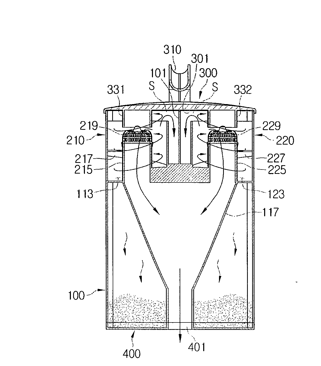
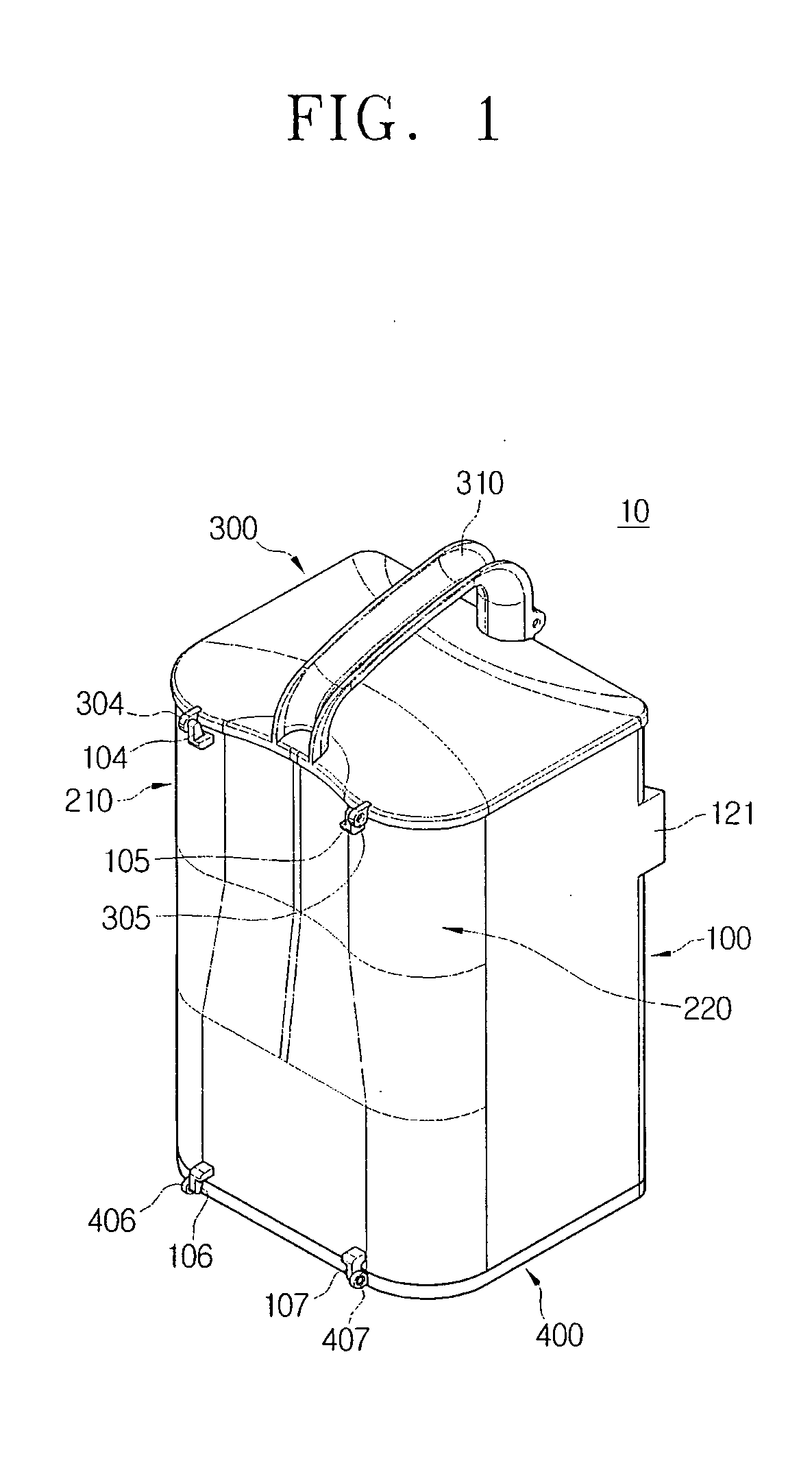
[0037]A cyclone dust-collecting apparatus 10 is detachably mounted in a main cleaner body (not illustrated) of a vacuum cleaner and is disposed on a suction flow path extending from a suction port body (not illustrated) to a suction source (not illustrated). Referring to FIG. 1, the cyclone dust-collecting apparatus 10 includes a body 100, a first cyclone unit 210, a second cyclone unit 220, a top cover 300, and a bottom cover 400.

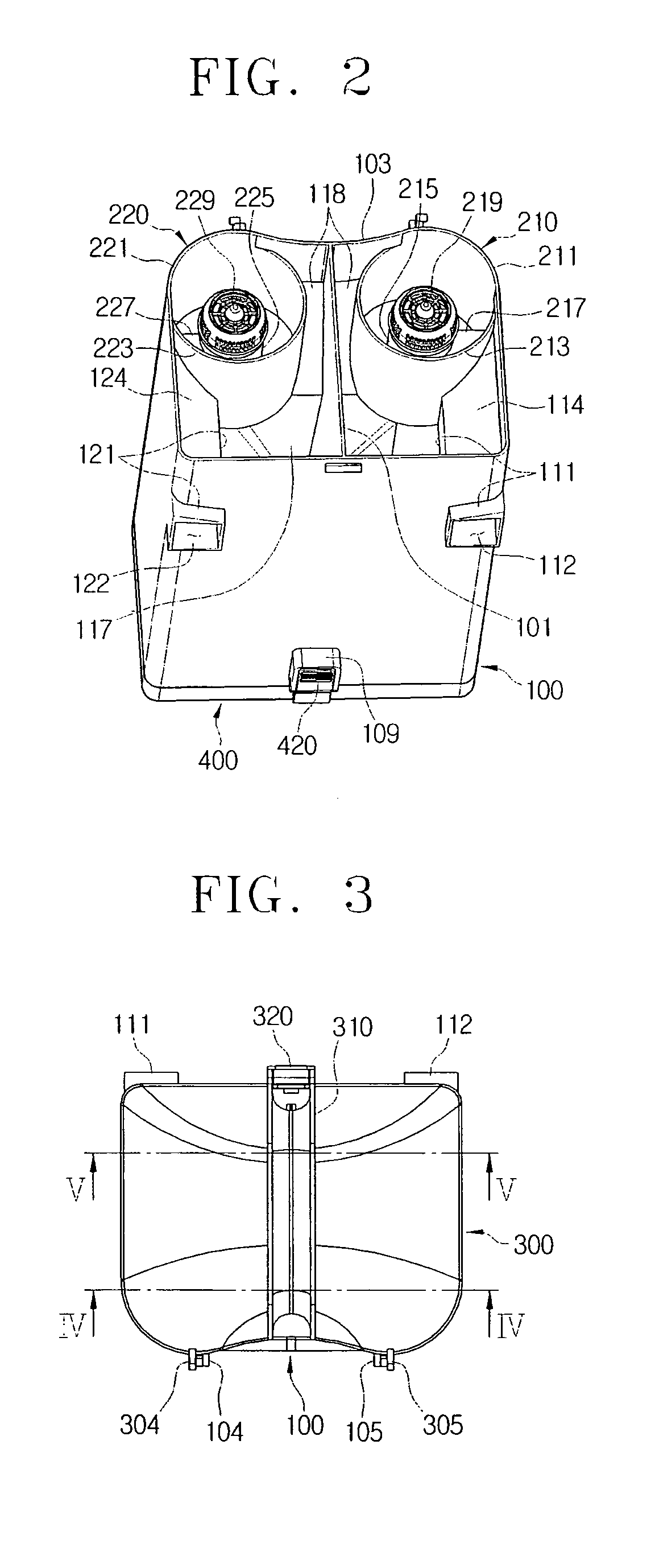
[0038]Referring to FIG. 2, the body 100 is formed in a substantially rectangular shape with opened top and bottom portions, and is divided into a first chamber 110 and a second chamber 120 by a partition 101 formed vertically on the center of the body 100. The first chamber 110 and second chamber 120 are substantially symmetrical to each other. The body ...


PUM

PropertyMeasurementUnit
distanceaaaaaaaaaa
forceaaaaaaaaaa
sizeaaaaaaaaaa

Abstract

A cyclone dust-collecting apparatus is provided. The dust-collecting apparatus is detachably mounted in a main cleaner body of a vacuum cleaner and disposed on a suction flow path extending from a suction port body to a suction source. The dust-collecting apparatus includes a body having an opened lower portion; at least one cyclone unit disposed to one side in the body to separate dust from air flowing into the body and discharge air from which the dust has been separated; and a bottom cover to open or close the lower portion of the body. The body has an inflow pipe penetrating the body from a rear portion of the body and connected to the cyclone unit and the inflow pipe has an inclined top surface.

Description

CROSS-REFERENCE TO RELATED APPLICATIONS[0001]This application claims the benefit under 35 U.S.C. § 119(a) Korean Patent Application No. 10-2008-14212, filed on Feb. 15, 2008, in the Korean Intellectual Property Office, and the entire disclosure of which is incorporated herein by reference.BACKGROUND OF THE INVENTION[0002]1. Field of the Invention[0003]The present disclosure relates to a cyclone dust-collecting apparatus for a vacuum cleaner, and more particularly, to a cyclone dust-collecting apparatus mounted in a vacuum cleaner to separate dust from air drawn inside the vacuum cleaner through a suction port body using a suction force and to collect the separated dust.[0004]2. Description of the Related Art[0005]Cyclone dust-collecting apparatuses for vacuum cleaners generally separate dust from air drawn inside the vacuum cleaner through a suction port body, collect the separated dust, and discharge air from which dust has been separated toward a suction motor.[0006]Such cyclone d...

Claims


Application Information

Patent Timeline
Patent Type & Authority Applications(United States)
IPC IPC(8): B01D45/12B01D35/30
CPCA47L9/1641A47L9/1691A47L9/1683A47L9/165A47L9/1616A47L9/10A47L9/16
Inventor OH, JANG-KEUN
Owner SAMSUNG GWANGJU ELECTRONICS CO LTD
Why Eureka
Try Eureka