Vehicle side fairing system

a technology for vehicles and fairings, applied in vehicle arrangements, roofs, transportation and packaging, etc., can solve the problems of increasing fuel consumption, increasing the amount of power needed to move a vehicle over land or through the air, and increasing the cost of operation

Inactive Publication Date: 2009-08-27
AEROFFICIENT
View PDF54 Cites 113 Cited by
  • Summary
  • Abstract
  • Description
  • Claims
  • Application Information

AI Technical Summary

Problems solved by technology

The amount of power needed to move a vehicle over land or through the air increases with the speed of the vehicle due to aerodynamic drag.
The amount of power necessary to overcome aerodynamic drag directly translates into increased fuel consumption, and thus cost of operation.

Method used


Image

  • Vehicle side fairing system
  • Vehicle side fairing system
  • Vehicle side fairing system

Examples


Embodiment Construction

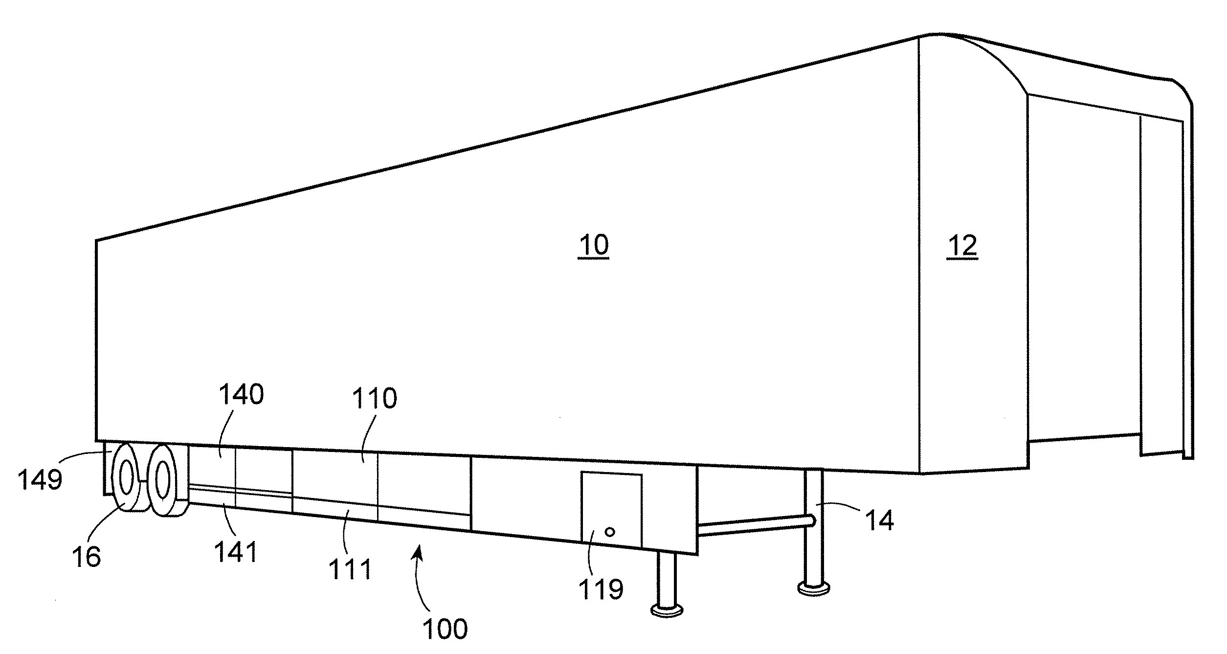
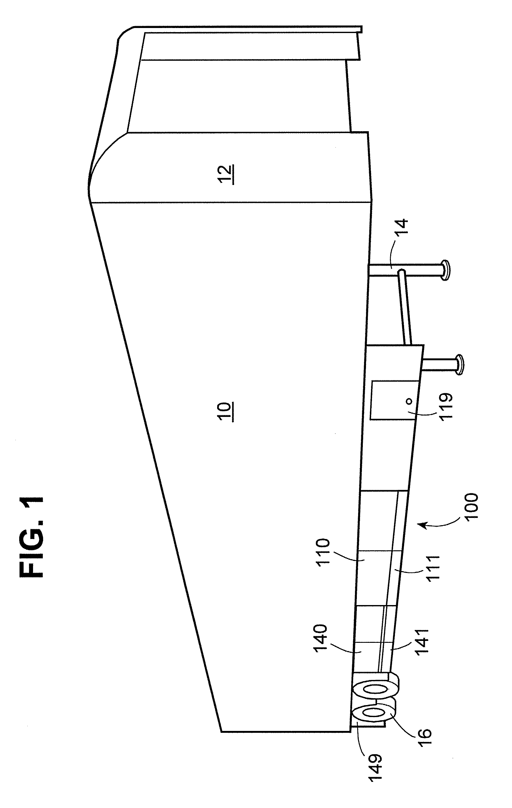
[0015]FIG. 1 generally depicts a truck trailer box 10 equipped with the side fairing invention, fairing assembly 100, described herein. It is also shown depicted with a front gap closing fairing 12, as more fully described in U.S. patent application Ser. No. 11 / 684,097. Trailer box 10 includes a wheel assembly 16 proximate to the rear of trailer box 10. As is conventional, wheel assembly 16 can be positioned fore and aft to accommodate variations in payload weight and distribution in trailer box 10. Trailer box 10 also includes a landing gear assembly 14, to permit trailer box 10 to sit level and to allow elevation of trailer box 10 so that a tractor (not shown) can be attached to and detached from trailer box 10.

[0016]Fairing assembly 100 is shown in FIG. 1 on the right side of trailer 10. It should be understood that there is a comparable fairing assembly 200 (not shown in FIG. 1) on the left side of trailer 10. The purpose of assemblies 100 and 200 is to inhibit the airstream fro...


PUM


Abstract

A vehicle side fairing having a first fairing panel fixedly secured to the underside of a trailer box, and a second fairing panel slidable mounted to plural cylindrical bars mounted on the underside of the trailer box in a fore and aft orientation. The second fairing panel is secured to the wheel set with a mechanical fastener that selectively joins and releases the second fairing panel and the wheel set.

Description

[0001]This application claims the benefit of U.S. Provisional Application No. 61 / 030,428, filed Feb. 21, 2008, and incorporated by reference herein.[0002]This invention relates to a system for improving the aerodynamic profile of vehicles by utilizing side vehicle fairing structures, especially for use on a tractor-trailer. The system improves fuel consumption without having a material adverse impact on vehicle operation or service procedures.BACKGROUND OF THE INVENTIONDESCRIPTION OF RELATED ART[0003]The amount of power needed to move a vehicle over land or through the air increases with the speed of the vehicle due to aerodynamic drag. The amount of power necessary to overcome aerodynamic drag directly translates into increased fuel consumption, and thus cost of operation.[0004]A variety of innovations aimed at reducing the aerodynamic drag of various transport vehicles, including tractor-trailer combinations, have been introduced in the prior art. These include efforts to make the...

Claims


Application Information

Patent Timeline
Patent Type & Authority Applications(United States)
IPC IPC(8): B62D35/00
CPCB62D35/001B62D25/168
Inventor HEPPEL, PETERGOLDING, HERBERTMEMERING, DOUGREIMAN, JAMESPETERSON, DANIELBOWMAN, WILLIAM
Owner AEROFFICIENT
Why Eureka
Try Eureka