Vibration actuator, lens barrel and camera
- Summary
- Abstract
- Description
- Claims
- Application Information
AI Technical Summary
Benefits of technology
Problems solved by technology
Method used
Image

Examples
Example
First Embodiment
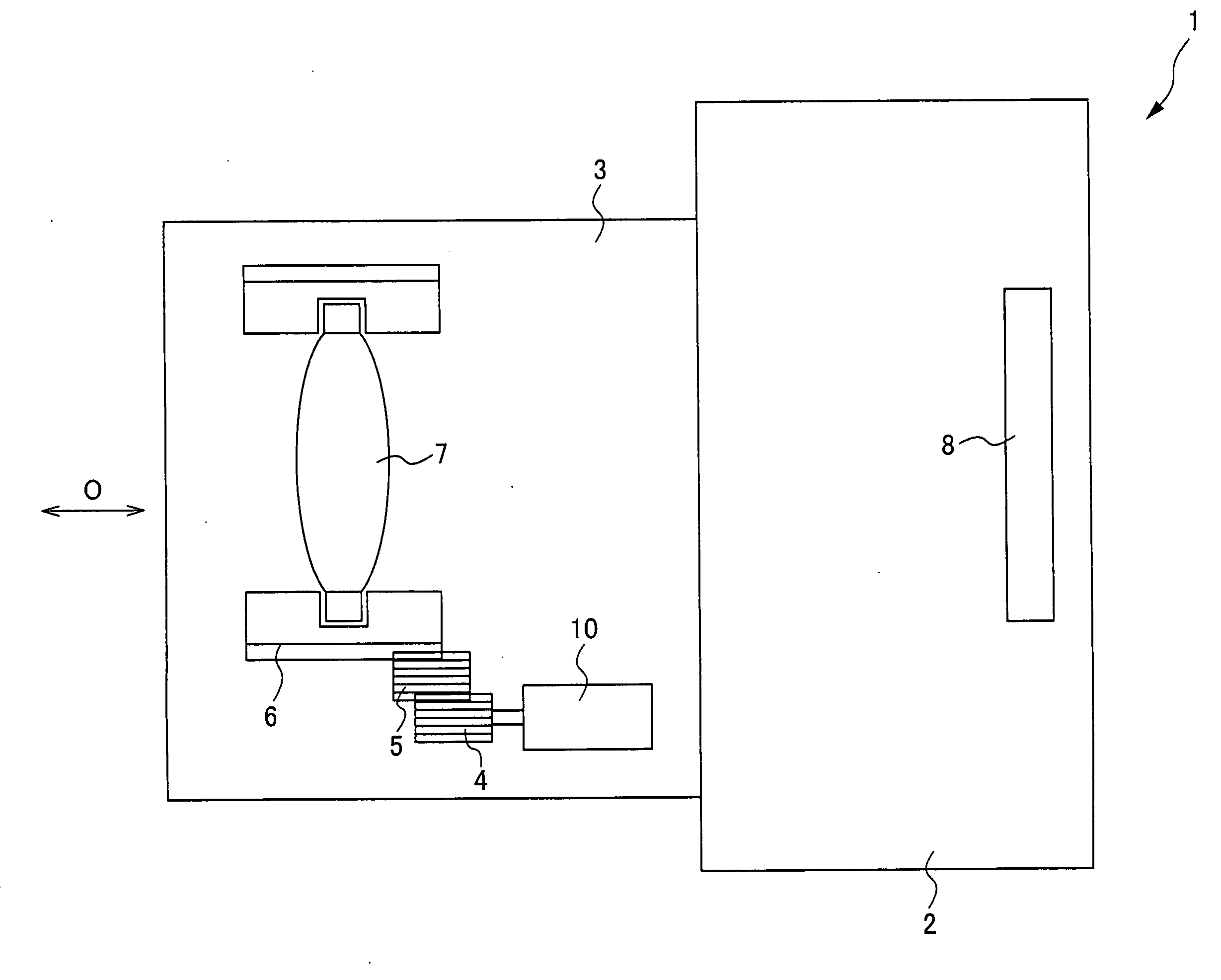
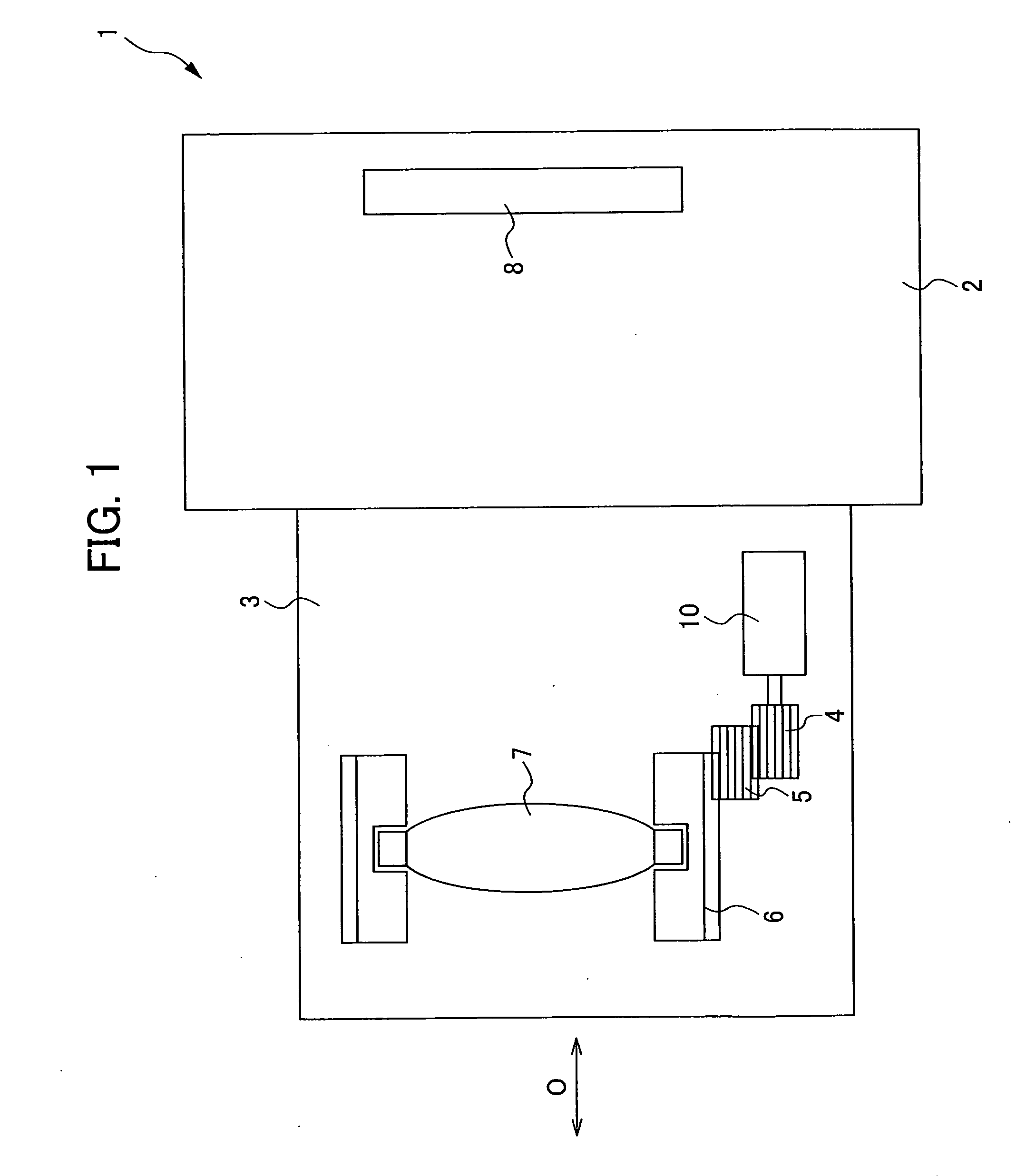
[0033]FIG. 1 is a view describing the camera 1 of the first embodiment.
[0034]The first embodiment of the camera 1 is provided with a camera body 2 including an imaging device and a lens barrel 3 including a lens 7.
[0035]The lens barrel 3 is an interchangeable lens which is detachable from the camera body 2. In the present embodiment, the lens barrel 3 illustrates an example that is an interchangeable lens, but this is not to be limiting; for example, it may be a lens barrel that is integral with the camera body.
[0036]The lens barrel 3 is provided with the lens 7, a cam tube 6, gears 4 and 5, the ultrasonic motor 10 and so forth. In the present embodiment, the ultrasonic motor 10 is used as a drive source that drives the lens 7 when focus-driving the camera 1. The driving force provided from the ultrasonic motor 10 is transmitted to the cam tube 6 via the gears 4 and 5. The lens 7 is retained in the cam tube 6. The lens 7 is a focusing lens that is moved in a directio...
Example
Second Embodiment
[0094]An ultrasonic motor of the second embodiment has a configuration substantially the same as the ultrasonic motor 10 illustrated in the first embodiment, except in that the form of the piezoelectric body 53 is different. Accordingly, portions that perform the same functions as in the above-described first embodiment are assigned the same reference numerals in the present embodiment, and duplicative descriptions are omitted as appropriate.
[0095]FIGS. 5A to 5C are views showing the piezoelectric body 53 of the second embodiment. FIG. 5A is a view in which a piezoelectric body side joining face 53a, which is joined to the joining face 12e of the vibrating body 12, is viewed from the vibrating body 12 side thereof. FIG. 5B is a view in which an other face 53b is viewed from the gear member 20 side thereof. FIG. 5C is a magnified view of a cross-section of the piezoelectric body 53 cut along the plane of arrows C3-C4 shown in FIG. 5A.
[0096]At the piezoelectric body 5...
Example
Third Embodiment
[0102]An ultrasonic motor of the third embodiment has a configuration substantially the same as the ultrasonic motor 10 illustrated in the first embodiment, except in that the form of the piezoelectric body 63 is different. Accordingly, portions that perform the same functions as in the above-described first embodiment are assigned the same reference numerals in the present embodiment, and duplicative descriptions are omitted as appropriate.
[0103]FIGS. 6A to 6C are views showing the piezoelectric body 63 of the third embodiment. FIG. 6A is a view in which a piezoelectric body side joining face 63a, which is joined to the joining face 12e of the vibrating body 12, is viewed from the vibrating body 12 side thereof. FIG. 6B is a view in which an other face 63b is viewed from the gear member 20 side thereof. FIG. 6C is a magnified view of a cross-section of the piezoelectric body 63 cut along the plane of arrows C5-C6 shown in FIG. 6A.
[0104]Substantially the same as at t...
PUM
 Abstract
Description
Claims
Application Information
 - R&D Engineer
- R&D Manager
- IP Professional
- Industry Leading Data Capabilities
- Powerful AI technology
- Patent DNA Extraction
Browse by: Latest US Patents, China's latest patents, Technical Efficacy Thesaurus, Application Domain, Technology Topic.
© 2024 PatSnap. All rights reserved.Legal|Privacy policy|Modern Slavery Act Transparency Statement|Sitemap