Eureka AIR delivers breakthrough ideas for toughest innovation challenges, trusted by R&D personnel around the world.

Hybrid vehicle and control method of hybrid vehicle

a hybrid vehicle and control method technology, applied in the direction of driver input parameters, electric devices, driver interactions, etc., can solve the problems of power insufficiency, poor emission, significant reduction of catalyst temperature, etc., to achieve sufficient catalyst performance, good vehicle driving performance, and sufficient catalyst performance

Inactive Publication Date: 2010-04-01
TOYOTA JIDOSHA KK
View PDF2 Cites 16 Cited by
  • Summary
  • Abstract
  • Description
  • Claims
  • Application Information

AI Technical Summary

Benefits of technology

[0004]In the hybrid vehicle and the control method of the hybrid vehicle, there would thus be a demand for preventing poor emission even in the event of a temperature decrease of a catalyst by a motor drive of the vehicle. In the hybrid vehicle and the control method of the hybrid vehicle, there would also be a demand for ensuring good driving performance of the vehicle even in the event of a temperature decrease of the catalyst by the motor drive of the vehicle.

Problems solved by technology

In the configuration of this prior art hybrid vehicle, a relatively long time duration of the motor drive may cause the temperature of the catalyst to significantly decrease at a time of restarting the operation of the engine.
When the motor drive decreases the temperature of the catalyst below a lower limit temperature of the specific performance-ensuring temperature range, the catalyst does not have the sufficient performance immediately after a restart of engine operation and causes the poor emission.
This measure, however, results in power insufficiency and failed output of the driver's required driving force, thus significantly lowering the vehicle driving performance.

Method used


Image

  • Hybrid vehicle and control method of hybrid vehicle
  • Hybrid vehicle and control method of hybrid vehicle
  • Hybrid vehicle and control method of hybrid vehicle

Examples


first embodiment

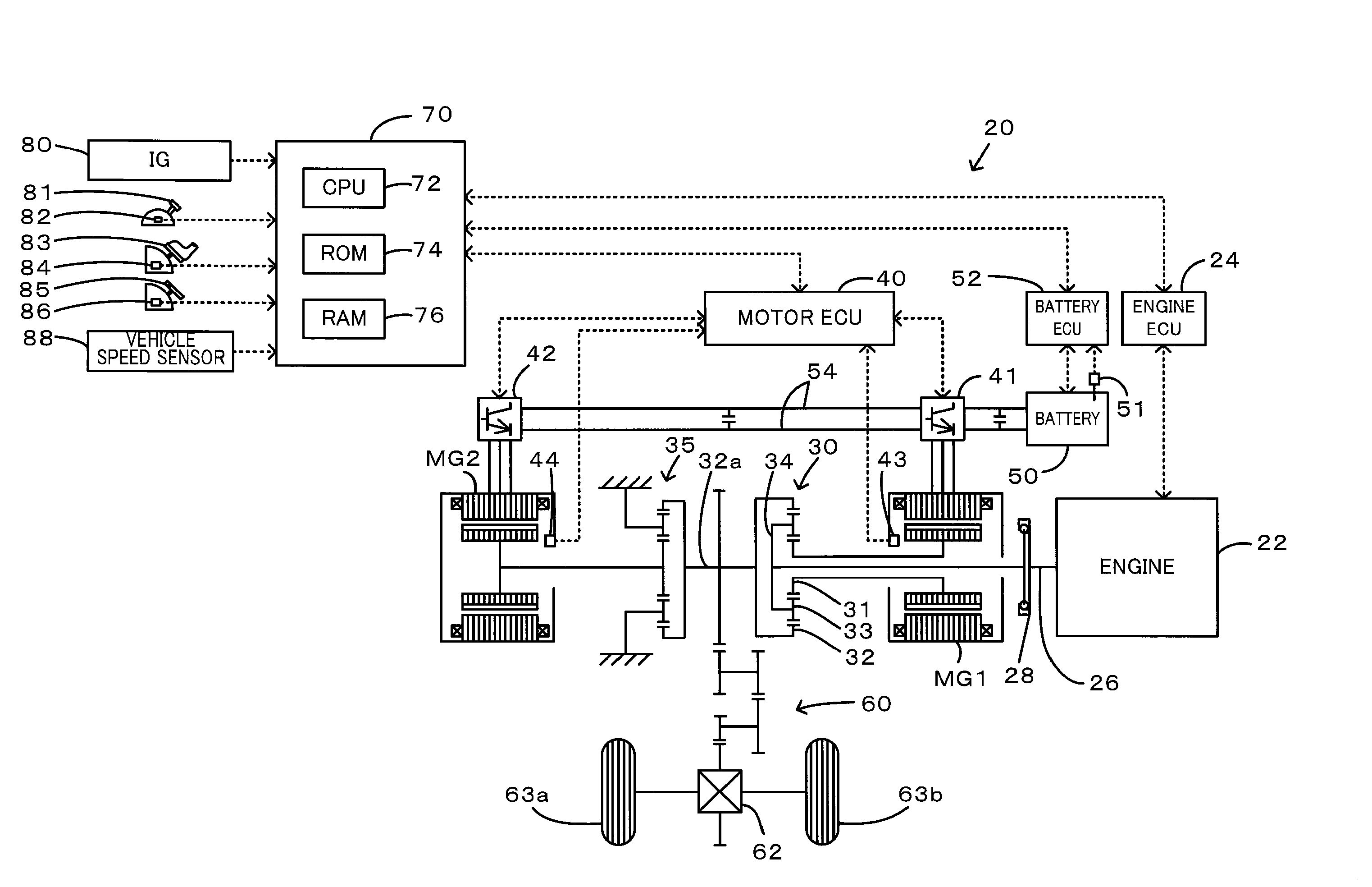
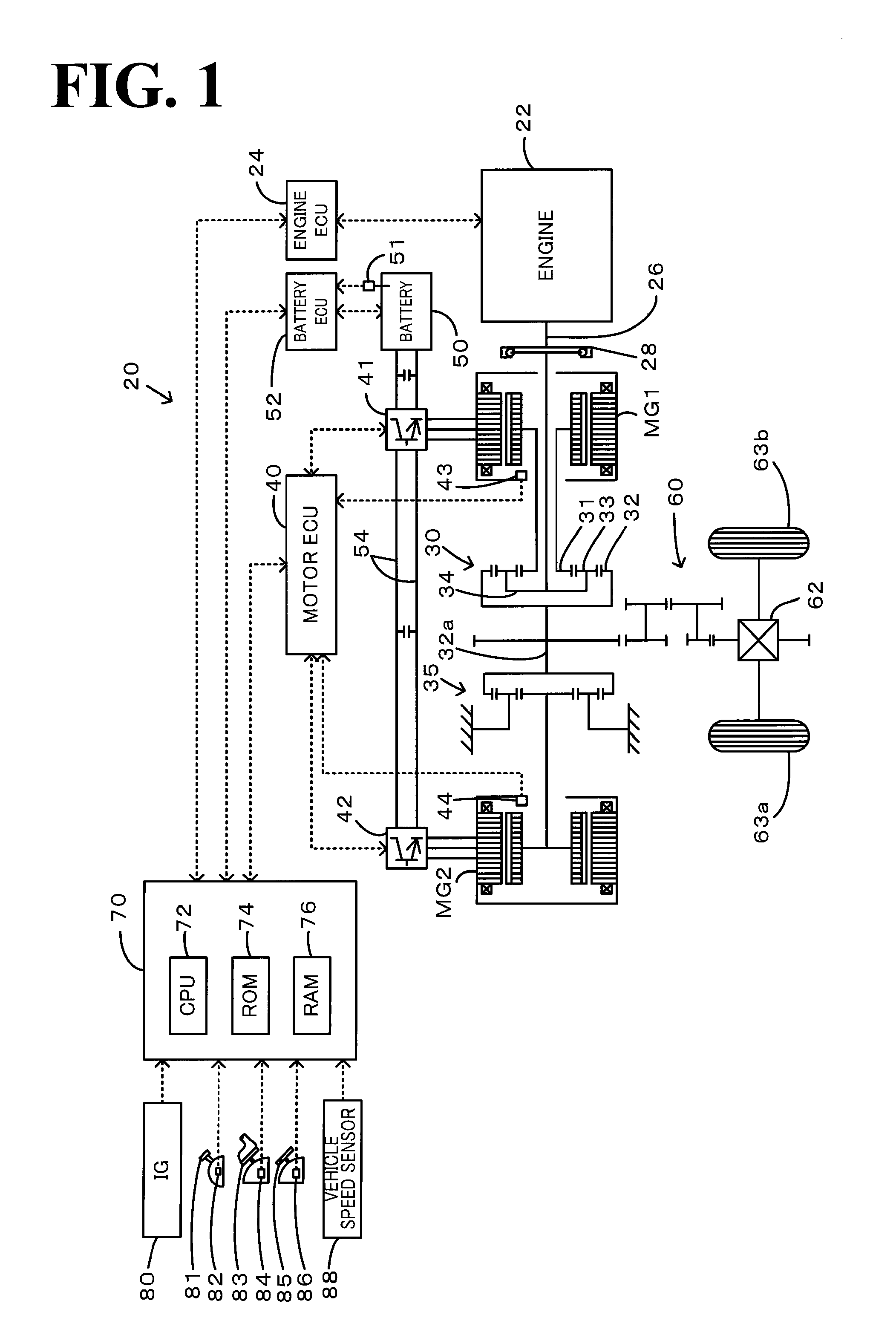
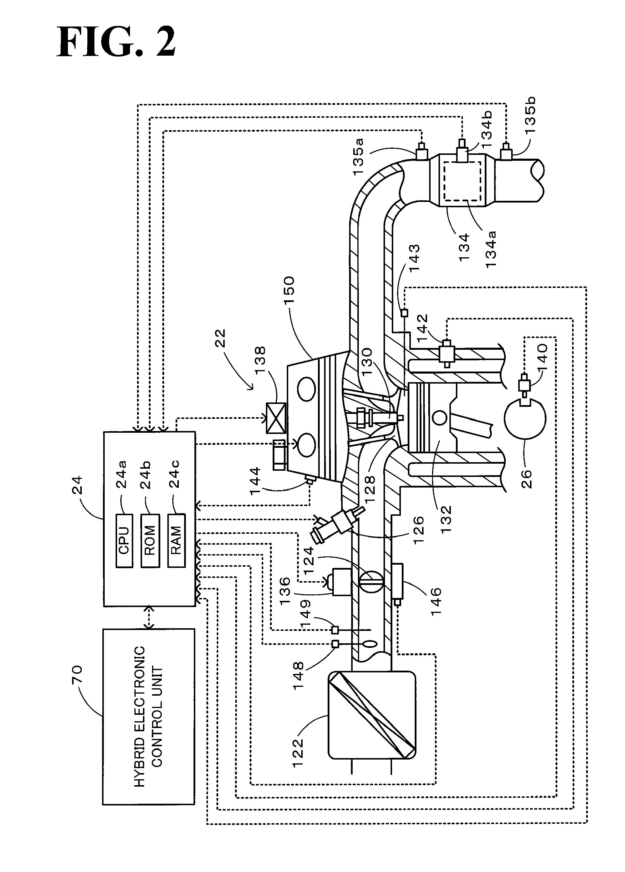
[0047]The following describes the operations of the hybrid vehicle 20 of the first embodiment having the configuration discussed above, especially a series of operations in response to a change from a motor drive of the hybrid vehicle 20 driven in the motor drive mode with only the output power of the motor MG2 in operation stop of the engine 22 to a hybrid drive of the hybrid vehicle 20 driven in the charge-discharge drive mode with a start of the engine 22. FIG. 3 is a drive control routine executed by the hybrid electronic control unit 70 in response to a change from the motor drive to the hybrid drive. This drive control routine is performed repeatedly at preset time intervals (for example, at every several msec). In the state of operation stop of the engine 22, the hybrid electronic control unit 70 performs a motor drive routine (not shown) and controls the engine 22 and the motors MG1 and MG2 to ensure output of a torque demand Tr*, which is set based on the accelerator openin...

second embodiment

[0069]In the hybrid vehicle 20B of the second embodiment described above, when the catalyst 134a has the significantly low catalyst temperature Tc and is expected to have only the poor catalyst performance immediately after a start of the engine 22 accompanied with a change from the motor drive to the hybrid drive, the torque demand Tr* is set with the drive restriction. The operation control of the engine 22 and the motors MG1 and MG2 is then performed with this torque demand Tr*. Such drive control with the drive restriction effectively prevents the poor emission compared with the conventional drive control without imposing the drive restriction, while ensuring the good vehicle driving performance compared with the simple catalyst warm-up operation of the engine 22. The drive restriction is imposed with the drive restriction value β set according to the catalyst temperature Tc and the EV drive time Tev. This arrangement ensures the adequate drive restriction based on the catalyst ...


PUM


Abstract

On a restart of an engine accompanied with a change from a motor drive of a hybrid vehicle to a hybrid drive, when a temperature of a catalyst in a catalytic converter located in an exhaust pipe of the engine decreases below a preset reference temperature to be out of a specific temperature range of ensuring sufficient catalyst performance, a power restriction value is set according to the catalyst temperature and an EV drive time representing a time duration of the motor drive. An engine power demand to be output from the engine is set under output restriction with this power restriction value. The engine and two motors are then controlled with the set engine power demand. This arrangement effectively prevents poor emission and ensures good driving performance of the vehicle even in the event of a temperature decrease of the catalyst by the motor drive of the vehicle.

Description

TECHNICAL FIELD[0001]The present invention relates to a hybrid vehicle and a control method of the hybrid vehicle. More specifically the invention pertains to a hybrid vehicle driven with output power of a motor and with output power of an internal combustion engine equipped with a catalytic converter located in an exhaust pipe and filled with a catalyst having capacity for reducing the toxicity of exhaust gas, as well as to a control method of such a hybrid vehicle.BACKGROUND ART[0002]One proposed configuration of a hybrid vehicle includes an engine, a planetary gear mechanism connected with an output shaft of the engine and with an axle of the vehicle, a generator linked to the planetary gear mechanism, and a motor arranged to output power to the axle. The hybrid vehicle of this proposed configuration is drivable with only the output power of the motor in the state of operation stop of the engine (see, for example, Patent Document 1). During a motor drive of this prior art hybrid ...

Claims


Application Information

Patent Timeline
IPC IPC(8): G06F19/00B60L50/16F01N3/20F02D29/02F02D45/00
CPCB60K1/02B60L2260/28B60K6/445B60K6/448B60K6/52B60W10/06B60W10/08B60W20/00F01N3/10F01N2560/025F01N2560/06F02D11/105F02D41/0235F02D41/062F02D2200/0802F02D2200/501F02D2250/26F16H2037/0866Y02T10/6239Y02T10/6243Y02T10/6265Y02T10/6286B60L11/123B60L11/14B60L11/1861B60L15/20B60L2210/40B60L2220/14B60L2220/52B60L2240/12B60L2240/36B60L2240/421B60L2240/423B60L2240/441B60L2240/443B60L2240/445B60L2240/80B60L2250/24B60L2250/26B60L2260/26B60K6/365B60L50/61B60L50/16B60L58/12B60W20/16B60W2540/10B60W2510/068B60W2710/0666B60W2710/0677B60W2710/0644B60W20/10B60W2710/083B60W2710/081Y02A50/20Y02T10/40Y02T10/62Y02T10/64Y02T10/70Y02T10/72Y02T10/7072B60W2530/12B60K6/22
Inventor ANDO, IKUO
Owner TOYOTA JIDOSHA KK
Why Eureka
Eureka Blog
Learn More