Generated wave propulsion water feature

a technology of propulsion water feature and generated wave, which is applied in wave producing pumps, liquid transfer devices, machines/engines, etc., can solve the problems of slow speed of sinking slides, insufficient water flow throughout the slide, and traditional water slides lacked the means to impart additional energy to individuals, etc., to relieve the pressure in the chamber

Active Publication Date: 2009-09-03
JOHNSON GARRETT T
View PDF30 Cites 5 Cited by
  • Summary
  • Abstract
  • Description
  • Claims
  • Application Information

AI Technical Summary

Benefits of technology

[0023]In another embodiment of the present invention, a water feature is disclosed for propelling a rider, the water feature comprising a water slide chute having a bottom, two sides, an upstream end, and a downstream end, wherein the chute is adapted to contain at least a portion of a body of water within the chute. The water feature comprises at least one wave generator adapted to generate at least one wave within the body of water, wherein the wave generator is located at the upstream end of the chute. The wave generator also includes a make-up fluid conduit, which is adapted to introduce fluid into the rear end of the chamber to relieve low pressure in the chamber; and a fluid control valve in fluid communication with the make-up fluid conduit and the rear end of the chamber, wherein the fluid control valve is adapted to control the introduction of fluid into the chamber. Actuation of the fluid control valve causes the make-up fluid to flow into the rear end of the chamber when the chamber reaches a predetermined low pressure.

Problems solved by technology

Because of the effect of friction and loss of energy caused by changing different directions (i.e., acceleration) away from a simple fall, serpentine slides may be limited to slower speeds.
In addition, in some cases the water flow may not be adequate throughout the slide for the individual to remain at speed.
Traditional waterslides lacked the means for imparting additional energy to the individual once they entered the slide—the course of the slide was traveled by expending potential energy.
Elevations were small and limited because each incline consumed energy and reduced speed.
Water jets involve localized energy transfers solutions that risk causing some discomfort for the rider.
Further, the imparting of additional energy extends the duration of a water slide.
Of course, this approach relies on placing structure within the area of activity in the channel, limiting its usefulness for certain activities.
A rider falling into a channel with flowing water might strike the structure or the tethering apparatus.
Thus, each of these features is limited in the means of propulsion, which is usually by the force of gravity (i.e., on both the individual and the water), or by the force of supplemental pressurized water gushes or jets.
However, the volume of pressurized air needed to achieve such effective operation in many embodiments has proven to be somewhat expensive.
Such a partial discharge of water creates smaller, inferior waves.
Of course, a release of excess compressed air that produces inferior waves is inefficient.
Reducing the volume and / or pressure of air released has also been discovered to be potentially problematic.
If the air released is inadequate to discharge fully the water from the chamber, then depending on the pressure during discharge and that of the surrounding body of water, several problems can arise.
First, the inadequate discharge of water from the chamber can cause inferior or low quality waves.
Second, the discharge of water has been observed to be reverse, in some cases halting the flow outward and rapidly reversing flow direction so as to return back to the chamber with a significant impact.
When the once expelled water returns into the chamber, it creates suction into the muzzle of the chamber, potentially posing a safety hazard to those in the wave pool.

Method used


Image

  • Generated wave propulsion water feature
  • Generated wave propulsion water feature
  • Generated wave propulsion water feature

Examples


Embodiment Construction

[0039]It is to be understood that the specific devices and processes illustrated in the attached drawings, and described in the following specification are exemplary embodiments of the inventive concepts defined in the appended claims. Hence, specific dimensions and other physical characteristics relating to the embodiments disclosed herein are not to be considered as limiting, unless the claims expressly state otherwise.

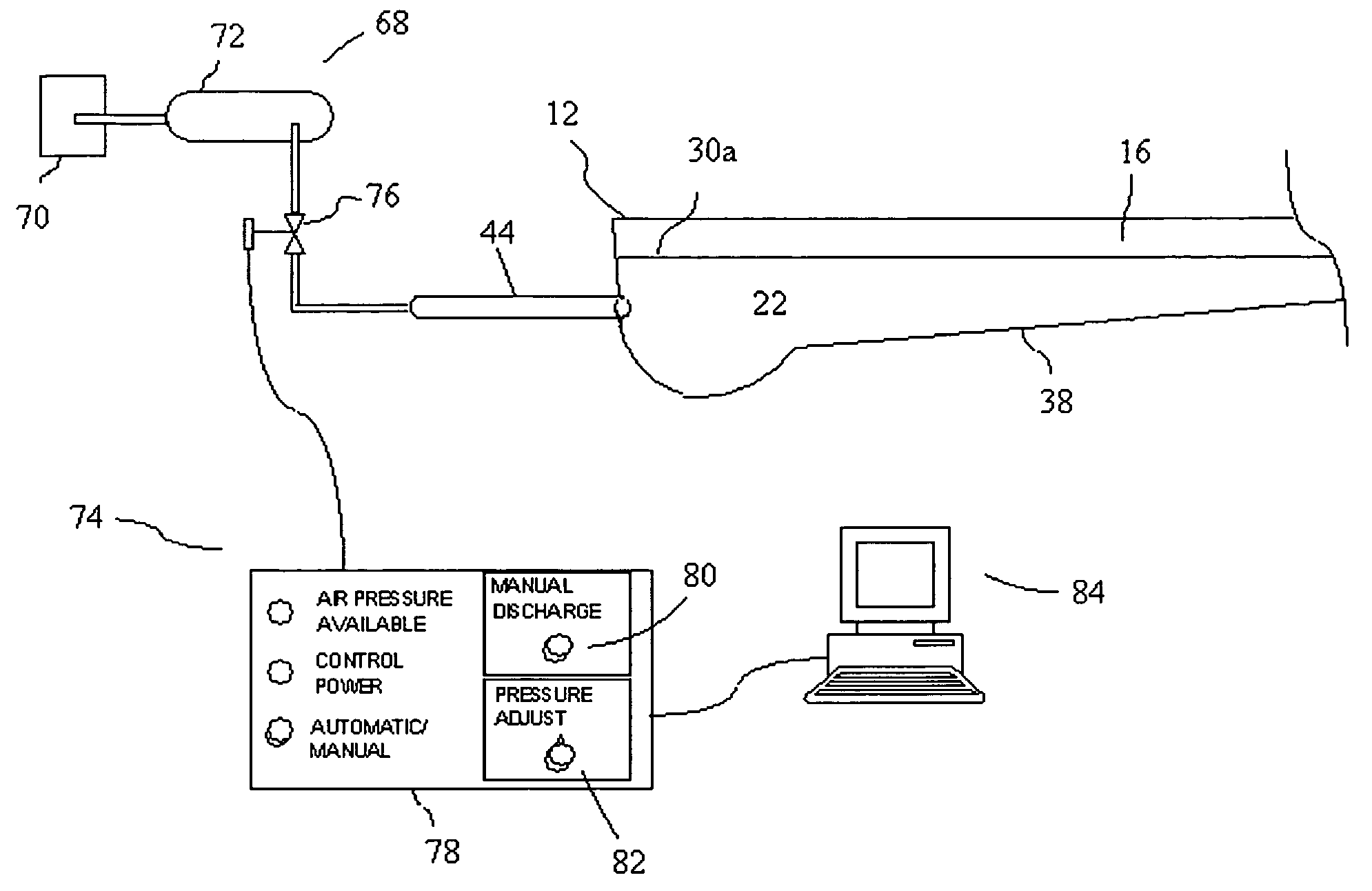
[0040]Preferably the wave generator used in the present invention will not interfere with the chute, will be scalable to various sizes or applications, will be remotely controllable, and will be capable of generating ridable waves. Embodiments of the present invention may include one or more pneumatic wave cannons for the generation of waves, as may be desired for the application. Ocean surface waves are primarily created by winds that cause variations in surface pressure. Wind duration, strength, and surface coverage area contribute to the resulting wave. In short,...


PUM


Abstract

An alternative propulsion or motive force for the riders of water features based on generated waves. A wave generator may be used to propel individuals or vessels within a chute for recreation or transportation. In one form, a pool or container having a body of water is configured to support an artificial wave generator which uses compressed gas to discharge water and generate a wave-like motion within a body of water. A source of make-up fluid is configured to mitigate internal low pressure conditions caused by the water discharge to enable effective wave generation with reduced quantities of compressed air. Portions of the waves generated in a pool may be captured in a variety of ways by chutes for stand-alone rides or for portions of chutes in water slides.

Description

CROSS REFERENCE TO RELATED APPLICATIONS[0001]The present application is a continuation-in-part of U.S. application Ser. No. 12 / 286,632 filed Oct. 1, 2008, which is: (i) a continuation-in-part of U.S. application Ser. No. 11 / 786,652 filed Apr. 12, 2007, now abandoned, which claimed the benefit of priority to U.S. Provisional Application Ser. No. 60 / 878,784 filed Jan. 6, 2007; and which was is (ii) a continuation-in-part of U.S. application Ser. No. 11 / 732,233 filed on Apr. 3, 2007, now U.S. Pat. No. 7,438,080, which claims the benefit of priority to U.S. Provisional Application Ser. No. 60 / 789,000 filed on Apr. 4, 2006. The present application is also a continuation-in-part of U.S. application Ser. No. 11 / 290,905 filed on Nov. 30, 2005, which claims the benefit of priority to U.S. Provisional Application Ser. No. 60 / 632,278, filed Dec. 1, 2004. All of the above applications are herein incorporated by reference in their entirety as if fully set forth herein.FIELD OF THE INVENTION[0002...

Claims


Application Information

Patent Timeline
Patent Type & Authority Applications(United States)
IPC IPC(8): E04H4/14A47K3/10
CPCF04D35/00Y10T137/3127
Inventor JOHNSON, GARRETT T.
Owner JOHNSON GARRETT T
Why Eureka
Try Eureka