Liquid tank structure of heat exchanger

a technology of liquid tank and heat exchanger, which is applied in the direction of subcoolers, refrigeration machines, lighting and heating apparatus, etc., can solve the problems of increasing the enclosed capacity of refrigerant and increasing the consumption amount of refrigerant, and achieve the effect of decreasing the necessary amount of refrigeran

Inactive Publication Date: 2009-09-03
CALSONIC KANSEI CORP
View PDF0 Cites 8 Cited by
  • Summary
  • Abstract
  • Description
  • Claims
  • Application Information

AI Technical Summary

Benefits of technology

[0008]In the liquid tank structure of the invention, the sloshing suppression member is arranged in the inner space of the liquid tank between the inlet port and the outlet port for suppressing the condensed refrigerate accumulated in the bottom portion of the liquid tank. Therefore, even when the condensed refrigerate which causes through the inlet part falls on the condensed refrigerate accumulated in the bottom portion of the liquid tank to disturb a liquid surface, the liquid surface is calmed down while and after the condensed refrigerant passes through the sloshing suppression member with the passing-through ability, and consequently its gas and its liquid are more surely separated from each other, only the condensed refrigerate is sent to the under cooling part through the outlet part.
[0009]Therefore, the liquid tank structure of the invention can prevent the condensed refrigerant from being sent to the under cooling part in a state where its gas and its liquid are unsufficiently separated from each other, due to a disturbance of the liquid surface of the condensed refrigerate in the liquid tank, and thereby it can obtain the effect in decreasing a necessary amount of the refrigerant.

Problems solved by technology

This causes a problem in that the condensed refrigerant 100, which is accumulated in the bottom portion of the liquid tank 100, is discharged to the under cooling part in a white turbidity state where the condensed refrigerant 103 contains the gas because the gas and the liquid thereof are remixed up due to the hard fall.
Accordingly, in the conventional liquid tank structure, there is a problem in that the enclosed capacity of the refrigerant increases too much, thereby increasing a consumption amount of the refrigerant which causes environmental problems in recent years.

Method used


Image

  • Liquid tank structure of heat exchanger
  • Liquid tank structure of heat exchanger
  • Liquid tank structure of heat exchanger

Examples


first embodiment

[0047]Hereinafter, a liquid tank structure of a heat exchanger of a first embodiment according to the present invention will be described. Incidentally, the liquid tank structure of the heat exchanger of the first embodiment is applied to a liquid tank which is mounted on a motor vehicle. Herein, a condenser corresponds to the heat exchanger of the present invention.

[0048]First, an entire structure of the heat exchanger with the liquid tank structure of the first embodiment will be described.

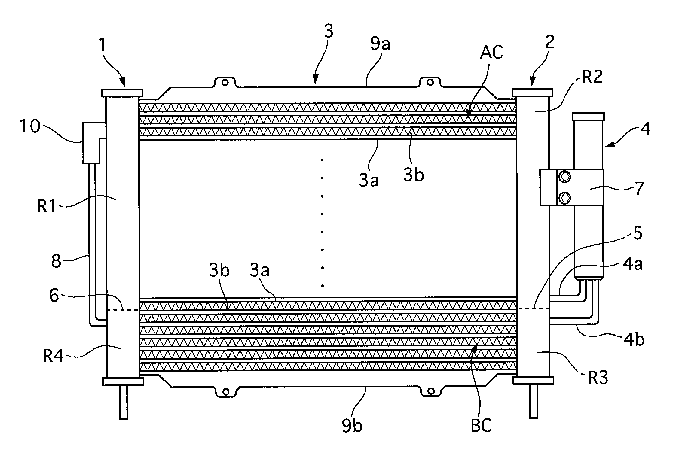
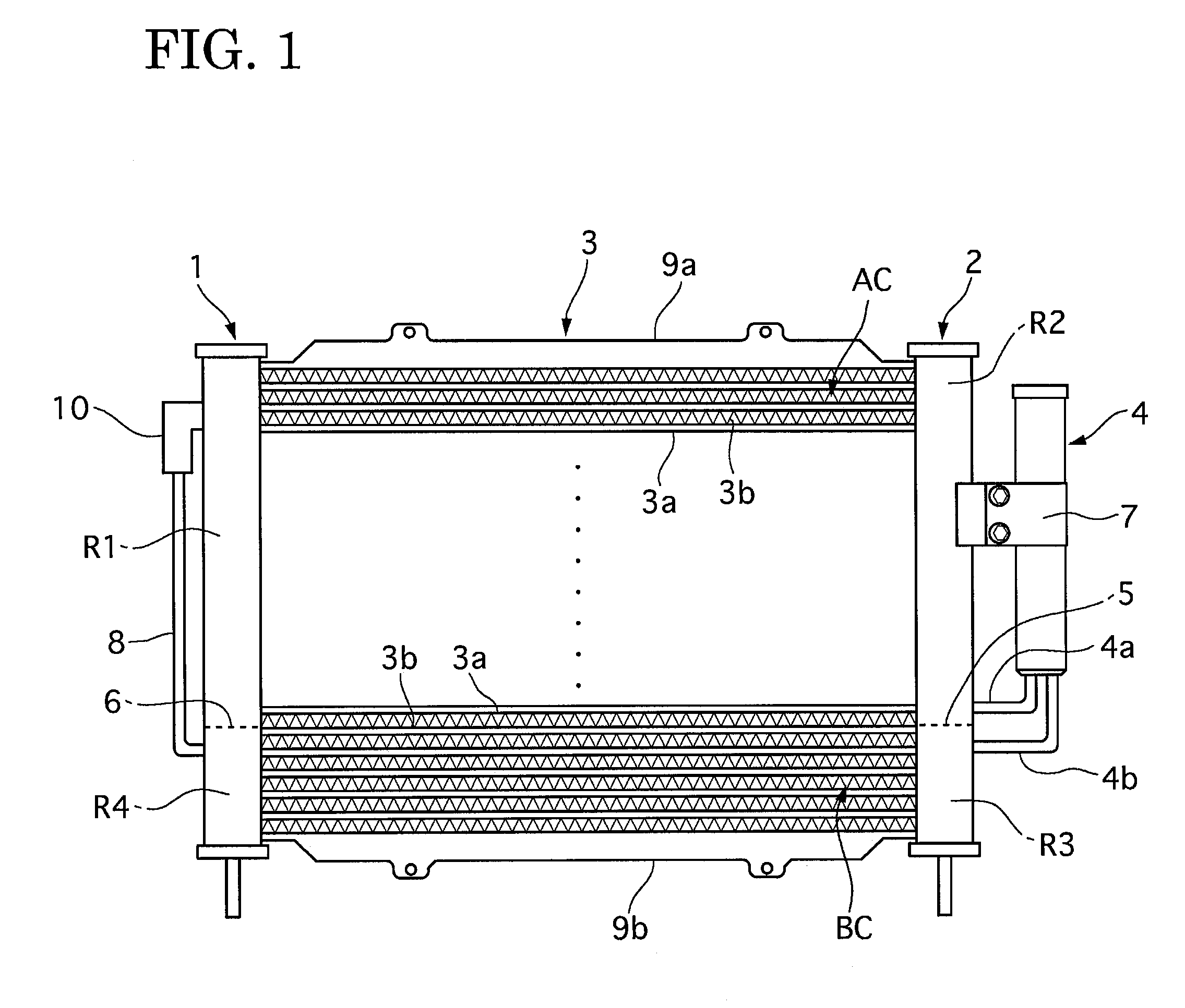
[0049]As shown in FIG. 1, the liquid tank structure of the heat exchanger of the first embodiment has a pair of headers 1 and 2, a condenser core 3 and a liquid tank 4.

[0050]The condenser core 3 is constructed by a plurality of tubes 3a and a plurality fins 3b, which are piled alternately to each other, and it is arranged between the pair of headers 1 and 2. The headers 1 and 2 are arranged at a right side and a left side, respectively, and their detail structure will later be described. Both en...

second embodiment

[0073]In a liquid tank structure of a heat exchanger of a second embodiment, as shown in an enlarged cross section view of a main part of a liquid tank of FIG. 6, the second embodiment is different from the first embodiment in that a sloshing suppression member 11 is arranged in a bottom portion of the liquid tank 4, and also in that the sloshing suppression member 11 is directly connected with an opening portion b1 formed on an end portion of an outlet-port side connecting pipe 4b. The other parts and portions of the second embodiment is constructed similarly to those of the first embodiment.

[0074]This means that, in the liquid tank structure of the second embodiment, falling condensed refrigerant passes through the sloshing suppression member 11, and then it is directly sent to an under cooling part BC through the outlet-port side connecting pipe 4b and the third room R3 of a header 2. Accordingly, the liquid tank structure of the second embodiment can obtain the effects similar t...

third embodiment

[0075]In a liquid tank structure of a third embodiment, it is different from the first and second embodiments in that a sloshing suppression member 11 is partially arranged in a state where the sloshing suppression member 11 covers an opening portion of an outlet-port side connecting pipe 4b while it does not cover all are of a bottom portion of a liquid tank. The other parts and portions of the third embodiment are constructed similarly to those of the first embodiment.

[0076]This means that, in the liquid tank structure of the third embodiment, falling condensed refrigerant passes through the sloshing suppression member 11, and then it is directly sent to an under cooling part BC through the outlet-port side connecting pipe 4b and the third room R3 of a header 2. Accordingly, the liquid tank structure of the third embodiment can also obtain the effects similar to those of the second embodiment.

Fourth Enbodiment

[0077]In the above-described liquid tank structures of the first to thi...


PUM


Abstract

In a liquid tank structure of a heat exchanger, a liquid tank 4 is attached to a heat exchanger having a heat exchanger core defining a condensation part AC and an under cooling part BC, and a pair of headers 1 and 2 each having an inlet part R1, R2 connected with the condensation part AC and an outlet part R3, R4. The condensed refrigerant from the inlet part R2 flows in the liquid tank 4 through an inlet port 1a of an inlet-port side connecting pipe 4a connected with the inlet part R2 of one header 2 of the pair of header. The condensed refrigerant Q accumulated in a bottom portion of the liquid tank 4 is discharged to the outlet part R3 through an outlet port b1 of an outlet-port side connecting pipe 4b connected with the outlet part R3 at a position under an inlet port a1. A sloshing suppression member 11, for suppressing a sloshing of the condensed refrigerant Q accumulated in the bottom portion of the liquid tank 4, has a passing-through ability of the condensed refrigerant and is provided in an inner space of the liquid tank 4 between the inlet port a1 and the outlet port b1.

Description

TECHNICAL FIELD [0001]The present invention relates to a liquid tank structure of a heat exchanger which is mounted on a motor vehicles and the like.BACKGROUND OF THE INVENTION [0002]Conventional liquid tank structures of heat exchangers are disclosed in Japanese Patents Laid-open No. (Tokkaihei) 11-316064 and No. 2000-46444. In these liquid tank structures, a heat exchange core, which includes a condensation part and an under cooling part, is provided with a pair of headers which fluidically connects the condensing part and the under cooling part. One of the headers is defined into an inlet part and an outlet part, where the inlet part is provided with an inlet port to be fluidically connected with the condensing part, and the outlet part is provided with an outlet port to be fluidically connected with the under cooling part. The other of the headers is defined into an inlet part and an outlet part, where the inlet part is fluidically connected with the under cooling part, being pr...

Claims


Application Information

Patent Timeline
Patent Type & Authority Applications(United States)
IPC IPC(8): F28F9/02
CPCF25B39/04F25B40/02F28F9/0246F25B2339/0441F25B2339/0446F25B43/003
Inventor SHINHAMA, MASAYOSHIMORISHITA, MASAHIRO
Owner CALSONIC KANSEI CORP
Why Eureka
Try Eureka