Moulding Device and Method

a moulding device and injection moulding technology, applied in the field of injection moulding devices and injection moulding methods, can solve the problems of limited temperature of moulded resin, long cooling time needed, and known injection moulding machines with inductive heating mould parts, etc., to achieve efficient production, reduce cooling flow, and increase heating efficiency

Inactive Publication Date: 2009-09-03
THERMAL CYCLIC TECH TCTECH I STOCKHOLM
View PDF6 Cites 9 Cited by
  • Summary
  • Abstract
  • Description
  • Claims
  • Application Information

AI Technical Summary

Benefits of technology

[0024]The object is also achieved by means of a method for injection-moulding, wherein liquid moulding compound is injected into a cavity defined by a first and a second mould part, at least one of said mould parts is heated during one phase of a production cycle, and said at least one part is cooled during another phase of the production cycle. During the cooling, a coolant is forced to flow through cooling ducts in said at least one mould part, and, during said heating, an oscillating current is applied to a coil having windings that run, at least part

Problems solved by technology

This imposes limitations upon the temperature of the moulded resin when injected into the cavity as well as upon the temperature of the cooling water.
Therefore, the time needed for cooling is quite long.
Thus, injection moulding machines with inductively heated mould par

Method used


Image

  • Moulding Device and Method
  • Moulding Device and Method
  • Moulding Device and Method

Examples


Embodiment Construction

[0036]There will now be described examples of injection-moulding devices.

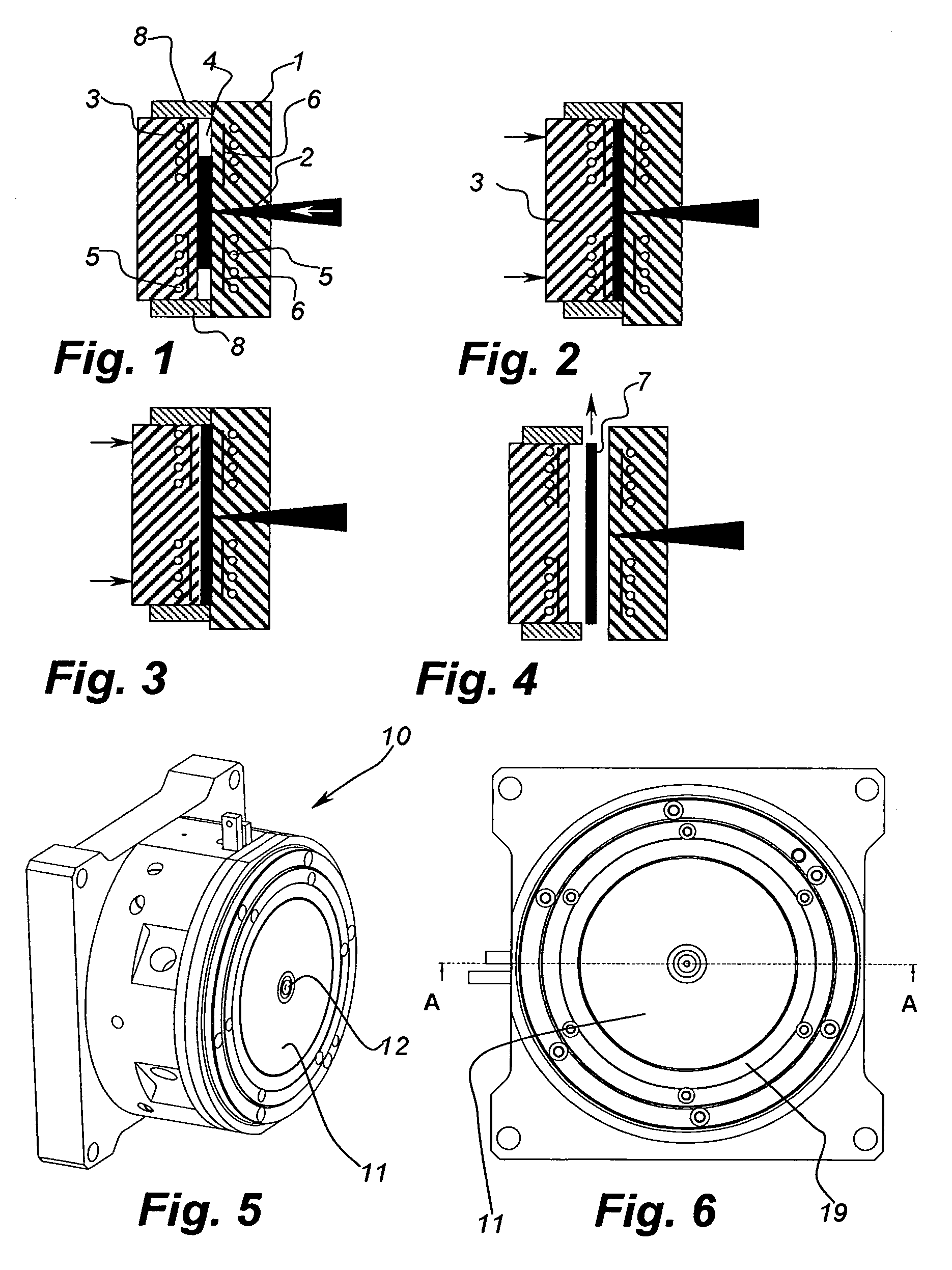
[0037]FIGS. 1-4 describe schematically steps in an injection-molding process utilizing an injection moulding device. More particularly, an injection compression cycle is schematically illustrated.

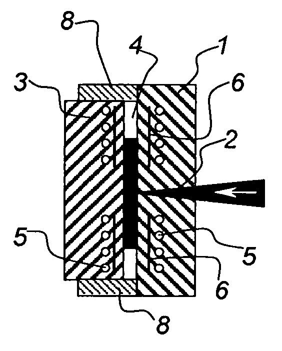
[0038]In the injection-moulding device, a first mould part 1 is fixed and comprises a resin injecting nozzle 2, which is fed by an extruder. Together with a second, moveable mould part 3 and a sub-part 8 on the second moveable part 3, the first mould part forms a cavity 4. The first and second mould parts further include means, in the form of coolant ducts 5, for cooling the mould parts in the vicinity of the cavity 4. Additionally, the first and second mould parts 1, 3 include means, in the form of inductor coils 6, for heating the mould parts in the vicinity of the cavity 4.

[0039]In the injection step, illustrated in FIG. 1, the heating means 6 are activated so as to heat the mould parts 1, 3 while hot resin is injec...


PUM

PropertyMeasurementUnit
Fractionaaaaaaaaaa
Electrical resistivityaaaaaaaaaa
Widthaaaaaaaaaa

Abstract

An injection-moulding device is disclosed, comprising at least a first (1) and a second (3) mould part, defining a mould cavity (4). At least one of the mould parts comprises cooling ducts (5), for cooling the mould part in the vicinity of a mould cavity surface (11), and heating means (6), for heating the mould part in the vicinity of the mould cavity surface. The cooling ducts (16) comprise grooves, in a carrier member (17), and the heating means comprises an inductive coil (18) having a plurality of windings, wherein at least a part of the inductive coil is placed in a cooling duct groove.

Description

CROSS REFERENCE TO RELATED APPLICATIONS[0001]This application claims benefit from European Patent application No. EP-05112704.1, filed Dec. 22, 2005, and U.S. provisional patent application No. 60 / 773,324, filed Feb. 15, 2006, both incorporated herein by reference.TECHNICAL FIELD[0002]The present invention relates to an injection-moulding device, a method for injection-moulding, and to information carriers and lightguide plates produced by means of such a device or such a method.BACKGROUND OF THE INVENTION[0003]Known injection-moulding devices, for producing objects of different kinds, usually comprise two main mould parts for defining a cavity. A first, fixed part has an injection nozzle, injecting the liquid moulding compound, typically a warm resin such as polycarbonate, into the cavity. A second mould part is movable in relation to the fixed mould part, such that it can be moved to open the cavity. The volume of the mould cavity, for forming the object, may be arranged in either...

Claims


Application Information

Patent Timeline
IPC IPC(8): B29C45/00B29C45/03B32B3/02G02B6/10
CPCB29C33/02B29C33/06B29C45/2642B29L2017/005B29C2045/7368B29C2045/7393B29C45/73
Inventor JADERBERG, JANOLIN, STEFAN
Owner THERMAL CYCLIC TECH TCTECH I STOCKHOLM
Why Eureka
Try Eureka