
Control valve for variable capacity compressor

a compressor and variable capacity technology, applied in the direction of valve operating means/release devices, machines/engines, positive displacement liquid engines, etc., can solve the problems of inability to control the speed of rotation and limitations on response, so as to reduce the vibration of the suction valve body, improve the efficiency of control, and waste coolant flow

Inactive Publication Date: 2009-03-17
FUJIKOKI CORP
View PDF6 Cites 7 Cited by
  • Summary
  • Abstract
  • Description
  • Claims
  • Application Information

AI Technical Summary

Benefits of technology

[0007]An object of the present invention is to realize a control valve that can perform control without waste of time or energy by realizing control with an even better response. A further object is to avoid the occurrence of vibration of the extraction valve body caused by the difference in pressure (Pc-Ps) between the crank chamber coolant pressure Pc and the suction coolant pressure Ps.
[0008]Yet a further object is to improve durability of the control valve by facilitating processing of the control valve and reducing the effect of coolant temperature on the solenoid exciting section of the control valve.

Problems solved by technology

Since the compressor that is employed in the refrigeration cycle of an air conditioner for an automobile is directly coupled with the engine by means of a belt, it is not possible to control the speed of rotation thereof.
However, in regulatory control of the crank chamber coolant pressure Pc of the aforesaid variable capacity compressor, there are limitations on the response thereof in that for example a prescribed time is required from when a fluctuation of the suction coolant pressure Ps takes place until completion of control.

Method used


Image

  • Control valve for variable capacity compressor
  • Control valve for variable capacity compressor
  • Control valve for variable capacity compressor

Examples


embodiment 1

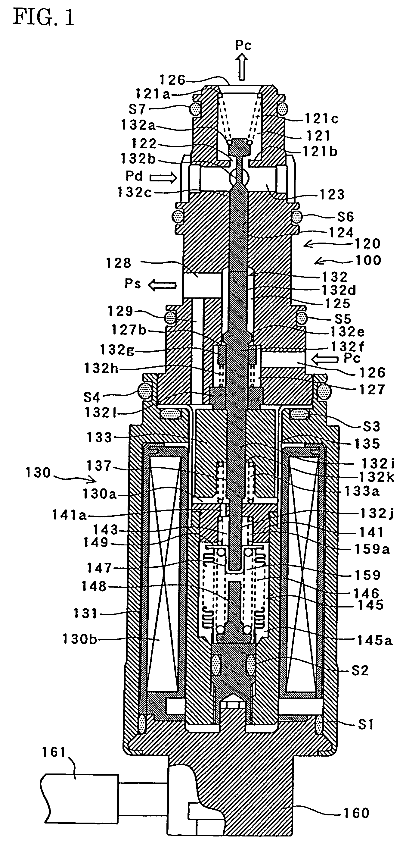
[0032]Embodiment 1 of a control valve according to the present invention is described with reference to FIG. 1 to FIG. 4.

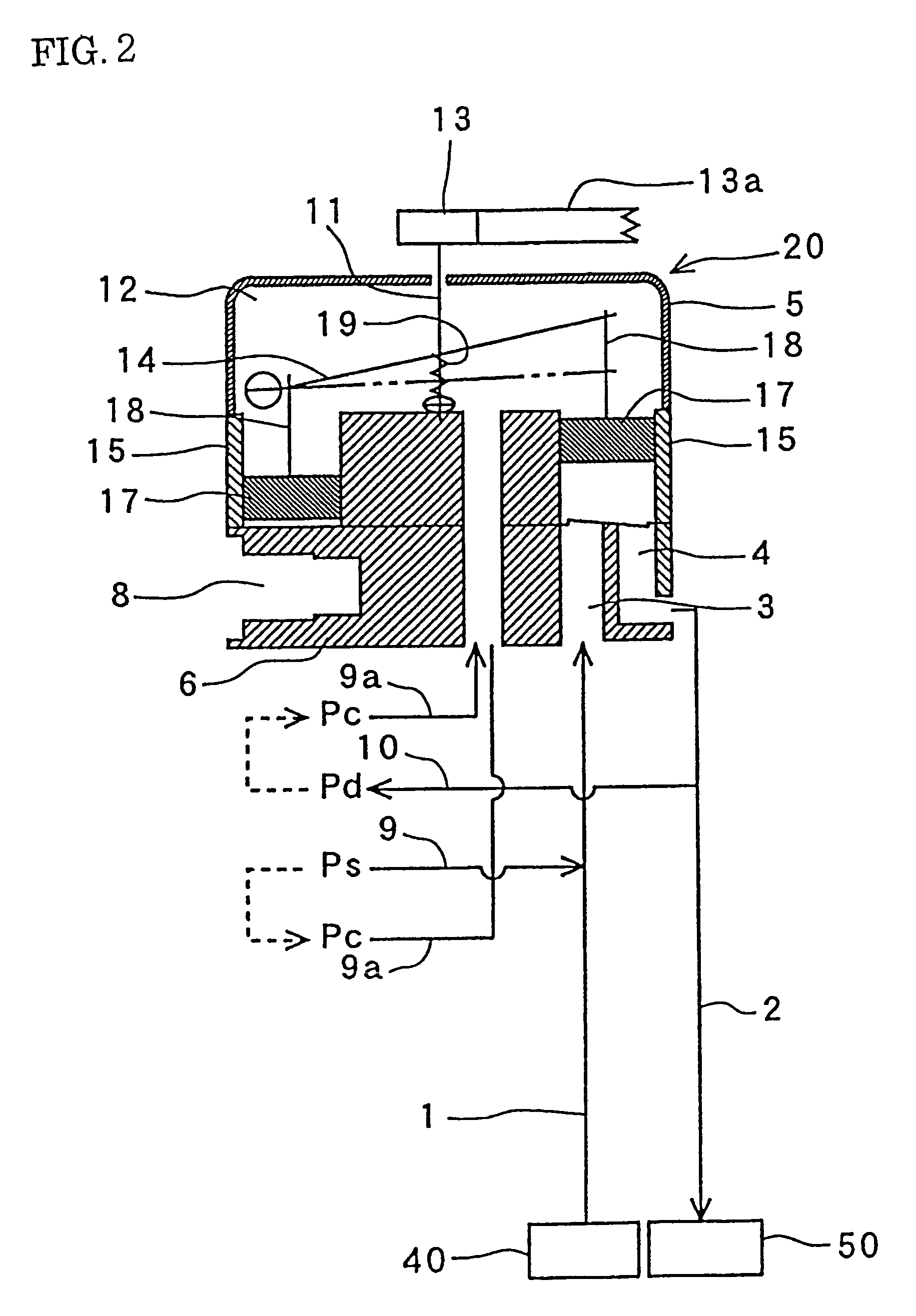
[0033]First of all, the variable capacity compressor wherein the control valve of embodiment 1 is employed will be described with reference to FIG. 2.

[0034]In FIG. 2, the reference numeral 20 indicates a variable capacity compressor of the inclined plate type, employed for example in a refrigeration cycle for air-conditioning of an automobile. Fluorocarbon gas is employed as the coolant, but application to a refrigeration cycle in which carbon dioxide is employed as the coolant would also be possible. This variable capacity compressor 20 is supported by a front housing 5 and a rear housing 6 integral with this front housing 5.

[0035]In FIG. 2, reference numeral 11 indicates a rotary shaft that is arranged within a crank chamber 12 (pressure-regulated chamber) that is constructed in gas-tight fashion. When the rotary shaft 11 is rotated by means of a pulley 13 that ...

embodiment 2

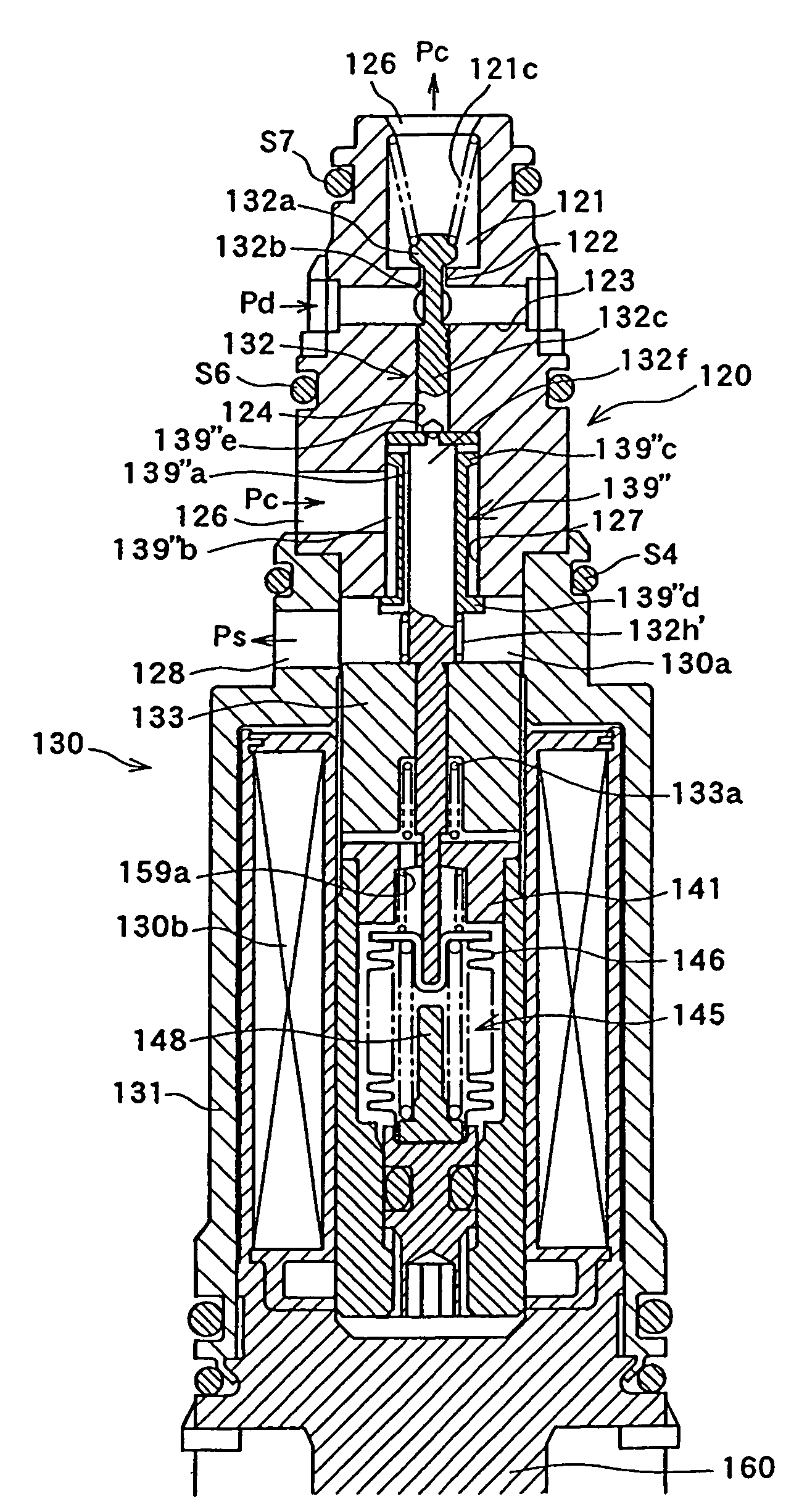
[0077]Next, embodiment 2 of the present invention is described with reference to FIG. 5 and FIG. 6. This embodiment is an improvement of embodiment 1 (FIG. 1). In the description of this embodiment, components that are common to embodiment 1 are given the same reference numerals in FIG. 5 and FIG. 6 as the symbols used in FIG. 1 and FIG. 2 and further description thereof is omitted here.

[0078]In embodiment 2, in order to reduce as far as possible the difference of the coolant pressures acting on the extraction valve body 139, it is arranged that the coolant pressures from above and below the extraction valve body 139 should be cancelled.

[0079]As shown in particular in FIG. 6, the extraction valve body 139 therefore comprises a tubular section 139a which extends in the vertical direction and is externally fitted onto an extraction valve body guide section 132f, a larger-diameter section 139b formed at the upper end of this tubular section 139a, and an inclined section 139c formed at ...

embodiment 3

[0083]Next, embodiment 3 of the present invention will be described with reference to FIG. 7. Embodiment 3 is a modified example of embodiment 1. In the description of this embodiment, components that are common to embodiment 2 are given the same reference numerals in FIG. 7 as those used in FIG. 5 and FIG. 6 and further description thereof is omitted here.

[0084]In this embodiment, the flow resistance of the fluid is further reduced by accommodating the stop 132e in the interior of the extraction valve body 139′ (at the position of the extraction valve chamber 127). Also, although in embodiment 2 the extraction valve closing spring 132h is mounted in compressed fashion between the lower part of the larger diameter section 139b of the extraction valve body 139 and the upper face of the spring receiving section 132l′, in embodiment 3 the extraction valve closing spring 132h′ is mounted in compressed fashion between the notched lower face 139′a of a cylindrical extraction valve body 13...


PUM


Abstract

In a control valve for a variable capacity compressor, coolant that is sucked in from a suction chamber through a suction conduit is compressed and delivered to a delivery chamber through a delivery conduit and the coolant pressure is controlled by an electromagnetic control valve. Opening / closing control of a gas supply valve body (gas supply side) that communicates with the delivery conduit and a crank chamber and of an extraction valve body (extraction side) that communicates with the crank chamber and the suction conduit is performed in accordance with the suction coolant pressure of the suction conduit. A crank chamber communication port communicates with the extraction valve chamber.

Description

BACKGROUND OF THE INVENTION[0001]1. Field of the Invention[0002]The present invention relates to a control valve of a refrigeration cycle employed in a variable capacity compressor, and in particular relates to a control valve for a variable capacity compressor that controls supply of coolant gas into a crank chamber from a delivery pressure region as required and to discharge of coolant gas into a suction-side region in the crank chamber.[0003]2. Description of the Related Art[0004]Since the compressor that is employed in the refrigeration cycle of an air conditioner for an automobile is directly coupled with the engine by means of a belt, it is not possible to control the speed of rotation thereof. A variable capacity compressor is therefore employed whose compression capacity (delivery rate) can be altered in order to obtain an appropriate cooling capability without being influenced by the rotational speed of the engine.[0005]This variable capacity compressor typically has a cons...

Claims


Application Information

Patent Timeline
Patent Type & Authority Patents(United States)
IPC IPC(8): F04B1/26F16K31/02F16K51/00F04B1/08F04B49/00F04B27/14F04B27/18
CPCF04B27/1804F04B2027/1813F04B2027/1827F04B2027/1831F04B2027/1854F04B2027/1859F04B27/1018F04B49/22F05B2210/12F05B2210/14Y10S417/00
Inventor OKII, TOSHIKIKUME, YOSHIYUKIWATANUKI, TORU
Owner FUJIKOKI CORP
Learn More