Alternative cooling path system for a marine propulsion device

Inactive Publication Date: 2009-03-03
BRUNSWICK CORPORATION
View PDF10 Cites 4 Cited by
  • Summary
  • Abstract
  • Description
  • Claims
  • Application Information

AI Technical Summary

Benefits of technology

[0011]A cooling system for a marine propulsion system, made in accordance with a preferred embodiment of the present invention, comprises a water pump, first and second cooling paths, and a valve having an inlet connected in fluid communication with the water pump, a first outlet connected in fluid communication with the first

Problems solved by technology

However, the provision of cooling water must be provided in such a manner that certain components are not cooled to temperatures lower than desirable thresholds while other components are not deprived of sufficient cooling water flow to maintain their temperatures below upper thresholds

Method used


Image

  • Alternative cooling path system for a marine propulsion device
  • Alternative cooling path system for a marine propulsion device
  • Alternative cooling path system for a marine propulsion device

Examples


Embodiment Construction

[0020]Throughout the description of the preferred embodiment of the present invention, like components will be identified by like reference numerals.

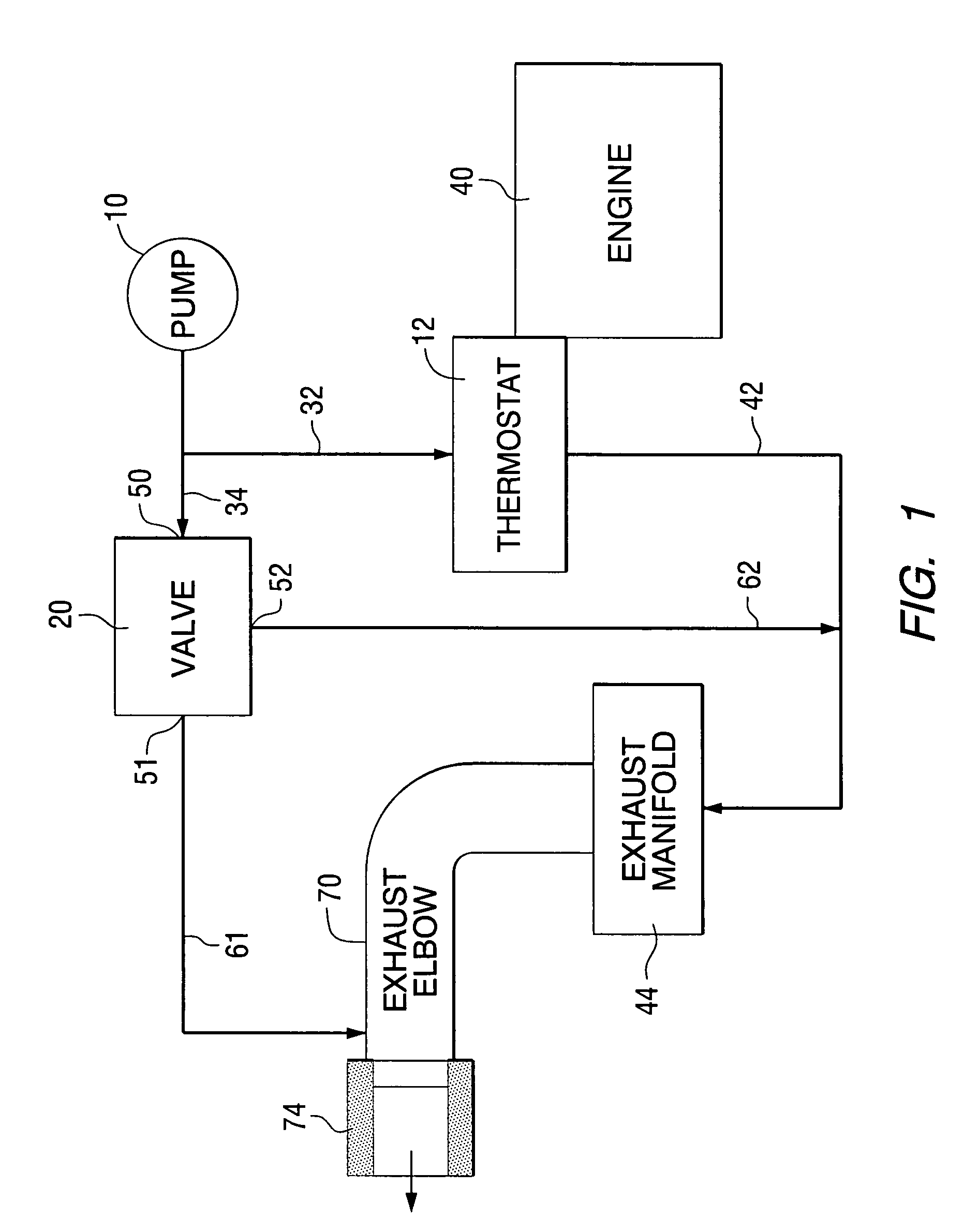
[0021]FIG. 1 is a simplified functional block diagram of a cooling system for a marine propulsion device. A pump 10, sometimes referred to as a sea pump, draws water from a body of water and provides that water to a thermostat 12 and a valve 20, through conduits 32 and 34, respectively. The thermostat 12 controls the flow of cooling water into the cooling jacket of an engine 40 in a manner that is generally well known to those skilled in the art. Some water is directed by the thermostat 12 to flow through conduit 42 toward an exhaust manifold 44 of the marine propulsion system.

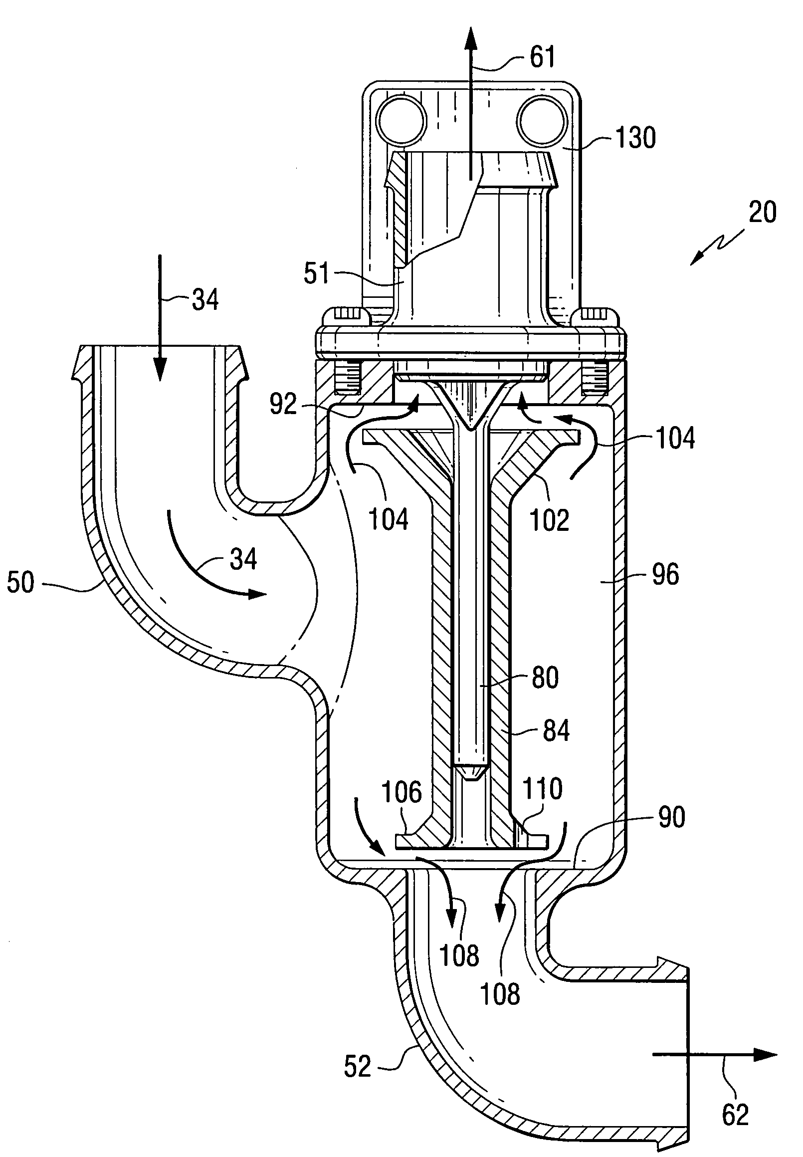
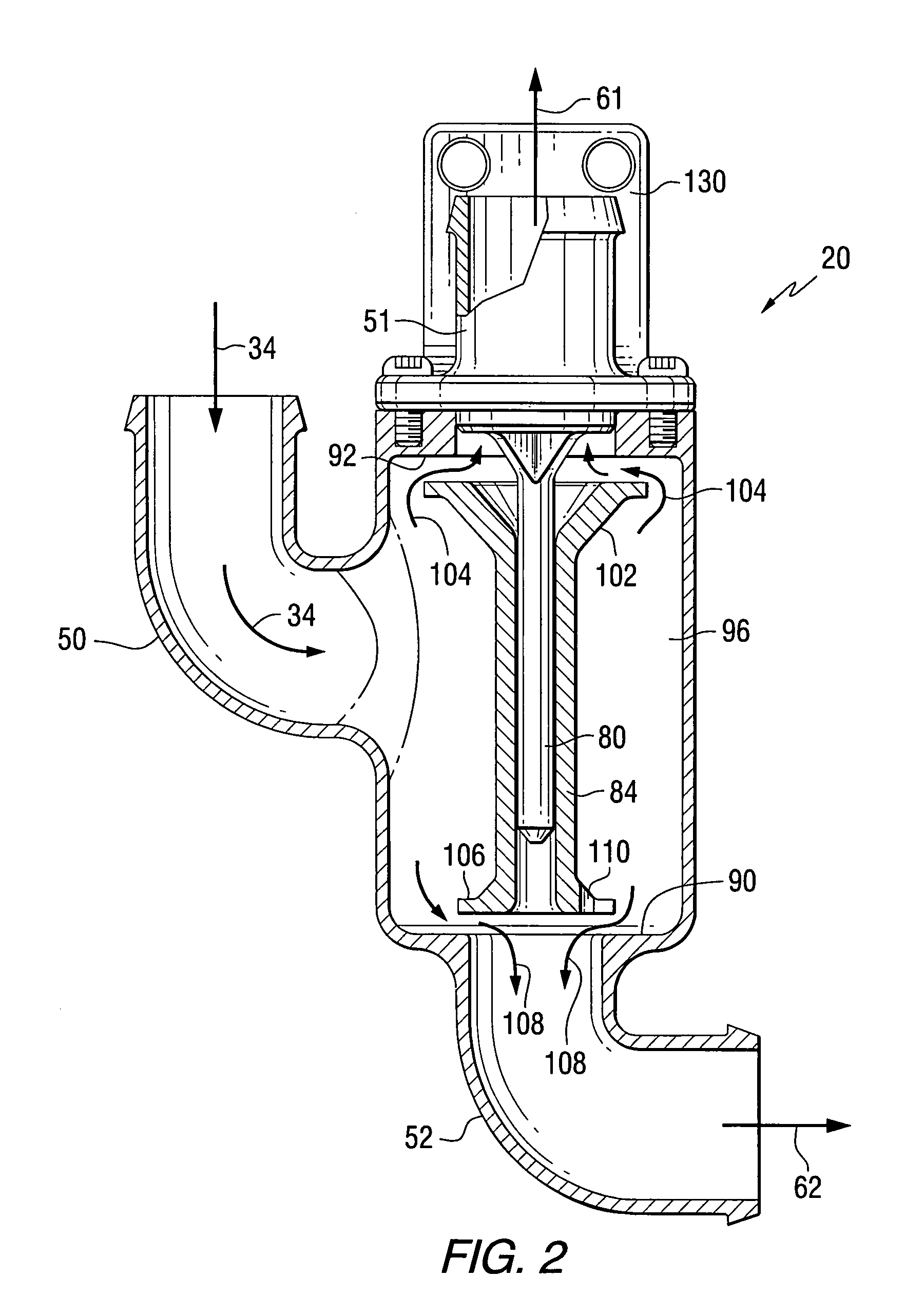
[0022]With continued reference to FIG. 1, some of the water flowing from the pump 10 flows to the valve 20. The operation of the valve 20 will be described in greater detail below. After the water flows into the inlet 50 of the valve, it is directed by the inner c...


PUM


Abstract

A cooling system of a marine propulsion device is provided with a valve that directs alternative flows of cooling water to portions of the marine propulsion system and apportions the cooling water flows in response to the speed of the water pump used to draw water from a body of water. Increasing pressures within the structure of the valve body change the proportion of water flowing through first and second coolant paths as engine speed increases.

Description

BACKGROUND OF THE INVENTION[0001]1. Field of the Invention[0002]The present invention is generally related to a cooling system for a marine propulsion device and, more particularly, to a cooling system valve that selectively routes cooling water to portions of the marine propulsion system based on the magnitude of incoming water pressure from a water pump.[0003]2. Description of the Related Art[0004]Those skilled in the art of marine propulsion systems are familiar with many systems and devices that are utilized to appropriately direct and / or restrict the flow of cooling fluid through conduits of the marine propulsion device. Some devices are provided to inhibit disadvantageous flow while others are used to encourage advantageous flow.[0005]U.S. Pat. No. 6,368,169, which issued to Jaeger on Apr. 9, 2002, discloses a marine engine cooling system with a siphon inhibiting device. A valve is provided for a marine engine cooling system and the purpose of the valve is to prevent the drain...

Claims


Application Information

Patent Timeline
IPC IPC(8): F02N1/00B63H21/10B63H21/14B63H21/38F01P3/20F02B61/04
CPCB63H21/14F02B61/04B63B2770/00F01P2007/146F01P2025/04F01P2050/04F01P2060/16B63H21/32B63H21/383F01P3/202
Inventor WHITE, BRIAN R.
Owner BRUNSWICK CORPORATION
Why Eureka
Try Eureka