
Liquid cooling server and automatic flow adjusting mechanism thereof

An automatic adjustment, server technology, applied in the server field, can solve the problems of heat dissipation, easy damage, energy waste, etc.

Active Publication Date: 2022-04-29
SUZHOU LANGCHAO INTELLIGENT TECH CO LTD
View PDF6 Cites 1 Cited by
  • Summary
  • Abstract
  • Description
  • Claims
  • Application Information

AI Technical Summary

Problems solved by technology

However, maintaining the maximum flow of coolant at all times will easily result in high power consumption, and the water pump will be in a high-load operation state for a long time, which is easy to be damaged, and the coolant with the maximum flow can only be effectively used when the server is running at high performance. In normal conditions, the server is not in a high-performance state for a long time. At this time, the heat generation is not large, and the heat dissipation demand is not high. This leads to excessive coolant flow, energy waste, and overcooling of heat dissipation.
In short, the liquid-cooled servers in the prior art cannot dynamically adjust the cooling liquid flow according to the actual heat generation and heat dissipation requirements of the server

Method used


Image

  • Liquid cooling server and automatic flow adjusting mechanism thereof
  • Liquid cooling server and automatic flow adjusting mechanism thereof
  • Liquid cooling server and automatic flow adjusting mechanism thereof

Examples

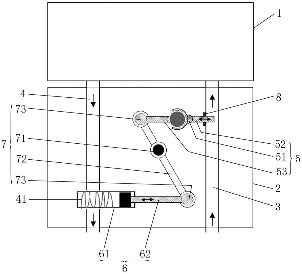

Embodiment Construction

[0026] The following will clearly and completely describe the technical solutions in the embodiments of the present invention with reference to the accompanying drawings in the embodiments of the present invention. Obviously, the described embodiments are only some, not all, embodiments of the present invention. Based on the embodiments of the present invention, all other embodiments obtained by persons of ordinary skill in the art without making creative efforts belong to the protection scope of the present invention.

[0027] Please refer to figure 1 , figure 1 It is a schematic diagram of the overall structure of a specific embodiment provided by the present invention.

[0028] In a specific embodiment provided by the present invention, the automatic flow adjustment device mainly includes an installation housing 2 , a water inlet pipe 3 , a water outlet pipe 4 , a mechanical control valve 5 , a driving mechanism 6 and a transmission mechanism 7 .

[0029] Wherein, the ins...


PUM


Abstract

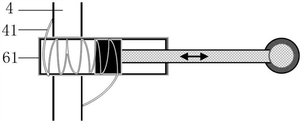
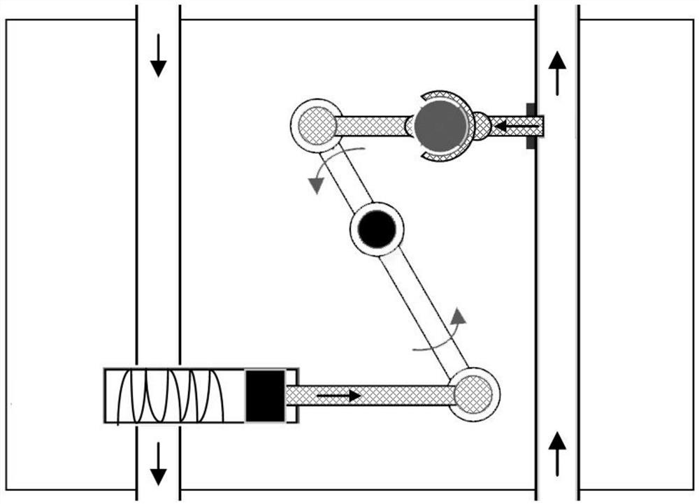
The invention discloses an automatic flow adjusting device which comprises a mounting shell, a water inlet pipe communicated with a water inlet of a server liquid cooling system, a water outlet pipe communicated with a water outlet of the server liquid cooling system, a mechanical control valve arranged on the water inlet pipe and used for controlling the water inlet flow of the water inlet pipe, and a driving mechanism arranged on the water outlet pipe. The transmission mechanism is connected between the output end of the driving mechanism and the control end of the mechanical control valve, the driving mechanism is filled with a working medium which is used for expanding with heat and contracting with cold under the temperature action of the water outlet pipe so as to drive the output end of the driving mechanism to reciprocate, and when the working medium expands with heat, the transmission mechanism drives the mechanical control valve to increase the opening degree; and when the working medium shrinks cold, the transmission mechanism drives the opening degree of the mechanical control valve to be reduced. The cooling liquid flow can be dynamically adjusted according to the actual heating condition and the heat dissipation requirement of the server, and the proper heat dissipation performance is guaranteed. The invention further discloses the liquid cooling server, and the beneficial effects of the liquid cooling server are as mentioned above.

Description

technical field [0001] The invention relates to the technical field of servers, in particular to an automatic flow adjustment mechanism. The invention also relates to a liquid cooling server. Background technique [0002] With the development of cloud computing and big data technology, the demand for server system resources increases accordingly. Processor suppliers realize the overall upgrade of system resources by improving the computing power of the processor and upgrading the multi-processor platform, which greatly improves the utilization of the entire system. Data processing capability, and the number of server external interfaces is increasing to meet the higher requirements of server system resources. In the era of big data explosion, especially with the development of artificial intelligence technology, the amount of data is increasing geometrically. The data center that undertakes these data calculations and storage has also shown a development trend of high dens...

Claims


Application Information

Patent Timeline
IPC IPC(8): G06F1/20
CPCG06F1/206G06F2200/201Y02D10/00
Inventor 张春宏
Owner SUZHOU LANGCHAO INTELLIGENT TECH CO LTD
Learn More