Superconducting electrical system

a superconducting electrical system and electrical system technology, applied in the direction of superconductor element usage, electric devices, transportation and packaging, etc., can solve the problem of redundancy and other problems, and achieve the effect of increasing power output, increasing input power, and increasing power outpu

Active Publication Date: 2016-04-26
ROLLS ROYCE PLC
View PDF7 Cites 2 Cited by
  • Summary
  • Abstract
  • Description
  • Claims
  • Application Information

AI Technical Summary

Benefits of technology

[0009]Providing an increased flow of coolant to electrical equipment allows it to be driven at a higher level of demand. Hence, if an item of electrical equipment fails, its loss can be compensated for by increasing the flow of coolant to the other items of electrical equipment and driving that equipment harder.
[0015]The electrical equipment may include a plurality of motors and increasing the power output of the electrical equipment includes increasing the rotational speed of one or more of the motors.
[0021]The method may include increasing the power output from one or more items of the electrical equipment when the flow of coolant is increased to that item of electrical equipment. The method may also comprise increasing the power output of one or more electrical generators in the electrical system by increasing the input power received from a prime mover.
[0022]Increasing the power output may include one or more of increasing the current flow in the equipment, increasing the electrical frequency supplied to the equipment, and increasing the switching frequency.
[0023]The electrical equipment may include a plurality of motors. Increasing the power output of the electrical equipment may include increasing the rotational speed of one or more of the motors.

Problems solved by technology

One problem presented by the use of superconducting technology in an aircraft arises from weight and the fact that there will likely be a requirement for some redundancy in any system to accommodate a fault.

Method used


Image

  • Superconducting electrical system
  • Superconducting electrical system

Examples


Embodiment Construction

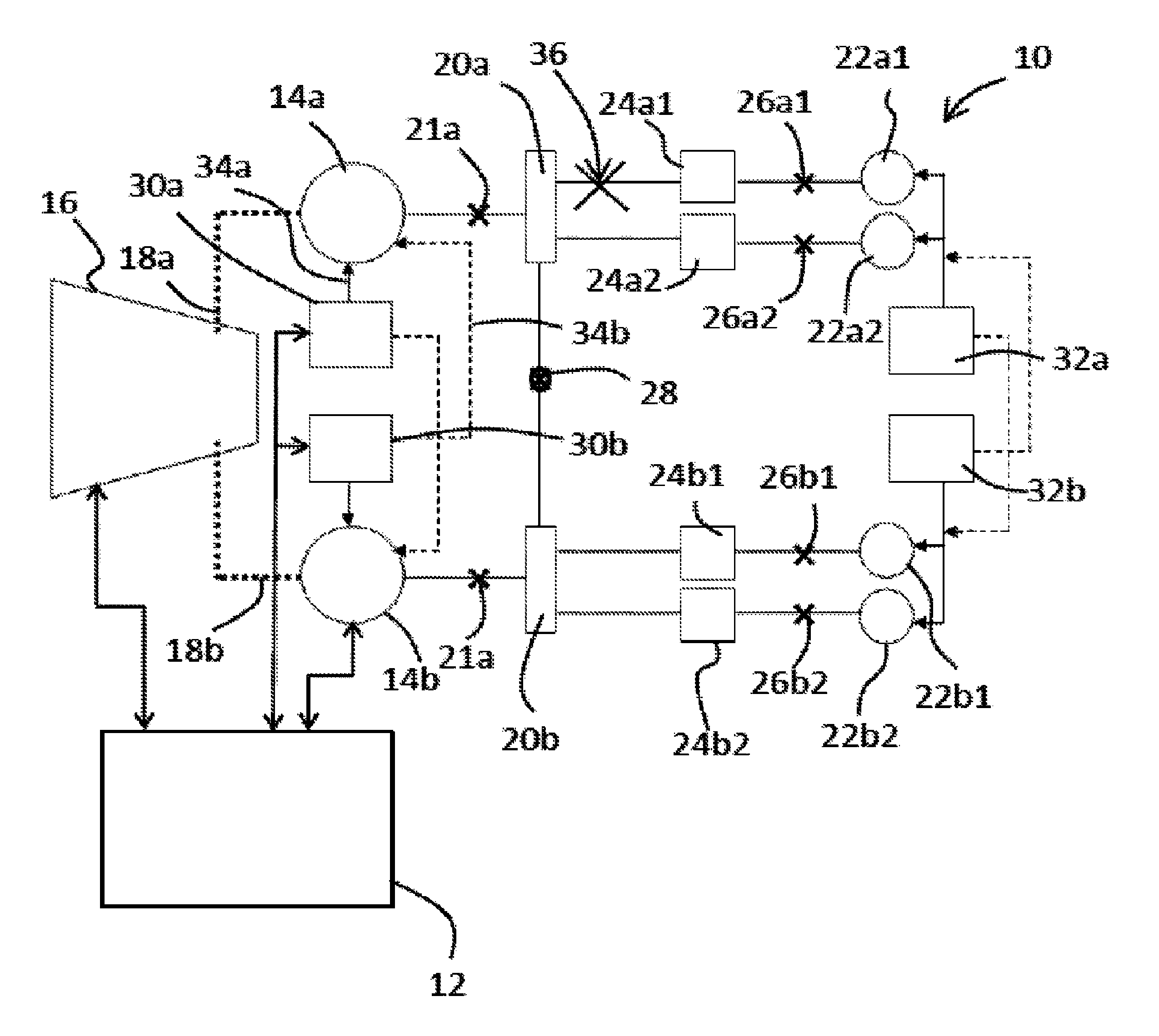
[0029]FIG. 1 shows a superconductive electrical network 10 which includes an electrical system and a cryogenic system, the operation of which are monitored by a controller 12.

[0030]The electrical network 10 described in this embodiment is part of an aircraft which utilises so-called distributed propulsion in which a plurality of electrically driven propulsive units are distributed about the airframe. However, the invention is not limited to this application and can be implemented on any superconducting electrical network.

[0031]The electrical system includes a plurality of pieces of superconducting electrical equipment. The superconducting electrical equipment includes superconducting generators, superconducting motors, refrigeration units, power electronic units in the form of convertors which are used to control the frequency and voltage within the network, and various electrical buses and wiring looms which include superconducting cables for example.

[0032]It will be appreciated th...


PUM


Abstract

This invention relates to a superconducting electrical network, comprising: an electrical system including a plurality of superconducting electrical equipment; a cryogenic system including one or more refrigeration units for providing coolant to the plurality of superconducting electrical equipment; a controller configured to control the flow of coolant to the plurality of superconducting electrical equipment, wherein the controller is configured to isolate the supply of refrigerant to one or more of the plurality of electrical equipment upon demand and increase the flow of coolant to one or more of the non-isolated plurality of electrical equipment.

Description

TECHNICAL FIELD OF INVENTION[0001]This invention relates to a superconducting electrical system and its method of operation. In particular, though not exclusively, this invention relates to superconducting electrical system for an aircraft.BACKGROUND OF INVENTION[0002]Conventional state of the art propulsion systems for large civil aircraft typically include one or more gas turbine engines placed under the wings of the aircraft. However, some studies have indicated that so-called distributed propulsion, which involves having numerous smaller propulsion units preferentially arranged around an aircraft, may provide some significant benefits in terms of noise reduction and fuel efficiency when compared with the current state of the art technology.[0003]One option for a distributed propulsion system is to have numerous electrically powered fan units located around the aircraft. However, early studies by the applicant have indicated that novel electrical technology will be required to im...

Claims


Application Information

Patent Timeline
Patent Type & Authority Patents(United States)
IPC IPC(8): B60L1/00H02G3/00B60L3/00B64D33/08E02D27/42B64D13/06
CPCE02D27/425B64D33/08B64D2013/0614Y02E40/622Y02E40/60
Inventor EDWARDS, HUW LLEWELYN
Owner ROLLS ROYCE PLC
Why Eureka
Try Eureka