Filler neck for filling a fluid system

a fluid system and filling technology, applied in liquid handling, machines/engines, packaging goods types, etc., can solve the problems of high risk of debris from spin welding process of caps, engine or water pump damage, etc., and achieve the effect of avoiding joint breakag

Inactive Publication Date: 2013-12-12
BEHR AMERICA
View PDF3 Cites 2 Cited by
  • Summary
  • Abstract
  • Description
  • Claims
  • Application Information

AI Technical Summary

Benefits of technology

[0006]The problem addressed in this invention is to provide a filler neck, which avoids breaking of joints and waiving of leak tests.
[0007]In an embodiment, a filler tube and a filler beginning connected with the filler tube creates the filler neck. Because of abstinence of spin weld of caps or plug to seal end of port radiator assemblies and engine coolant systems are protected for damages. The coolant flow is improved and the pressure drop during the filling cycle is reduced. Consequently, customer costs are reduced.
[0008]In addition, the filler tube and the filler beginning are formed in one piece. A leak test of the filler neck can consequently be omitted. Hence, the fill speed is improved.
[0009]Furthermore, the filler neck comprises rotary device. Hence, fixing of the filler neck to the fluid system can be achieved by very simple handling.
[0010]In another aspect of the invention, the filler tube can be curved wherein the filler beginning is directed approximately perpendicular to a fluid system opening. The new design of filler neck allows an easy method for filling the fluid into the fluid system like the radiator or the engine coolant system, because the fluid flow is improved.
[0013]Furthermore, the flanged socket is fixed perpendicularly to the filler beginning. Consequently, the pressure drop is reduced during the filling cycle.

Problems solved by technology

Additionally, a high risk exists of debris from spin welding process of caps.
The debris can cause breaking off from joint which can lead to an engine or water pump damage.

Method used


Image

  • Filler neck for filling a fluid system
  • Filler neck for filling a fluid system

Examples


Embodiment Construction

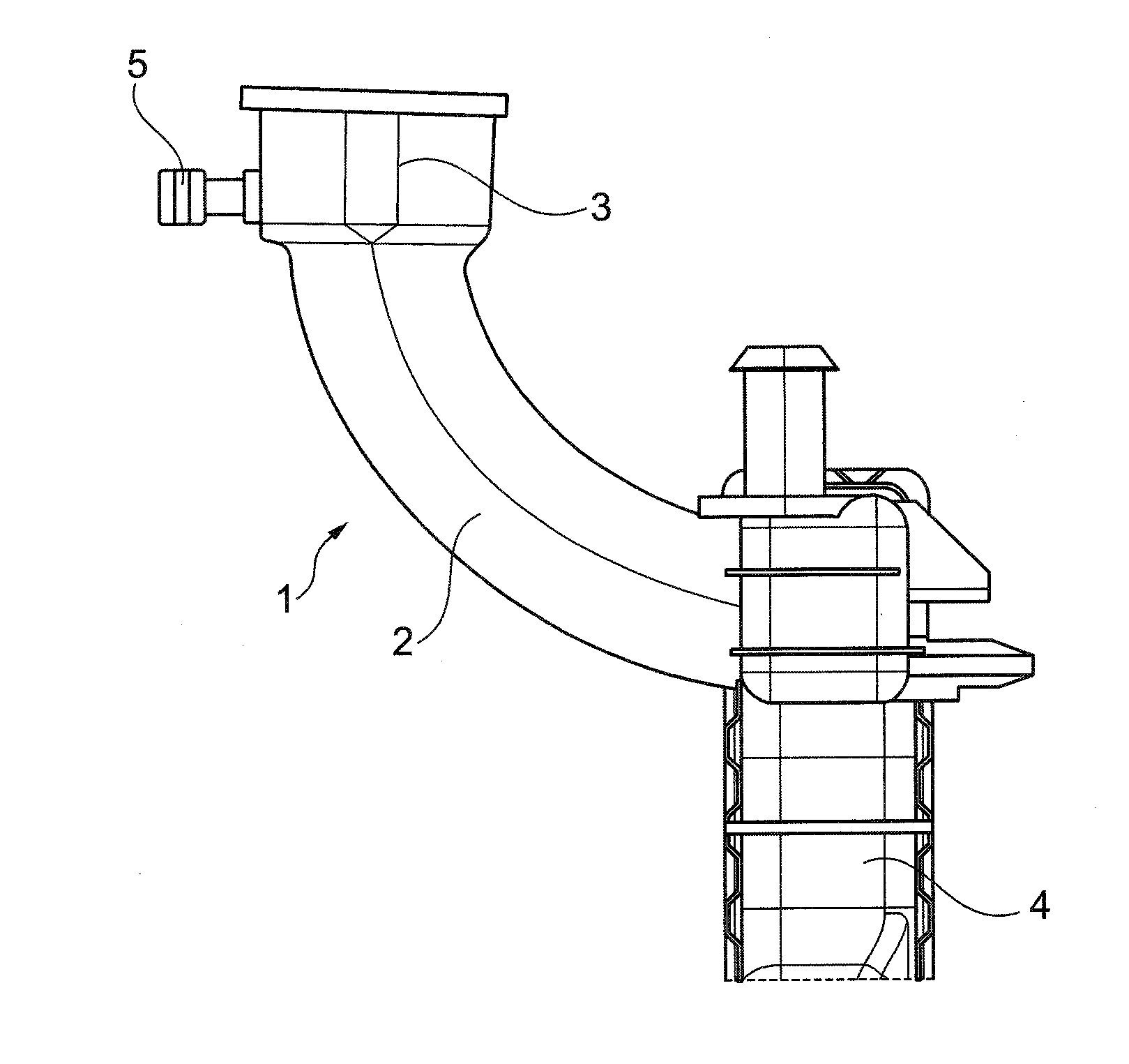
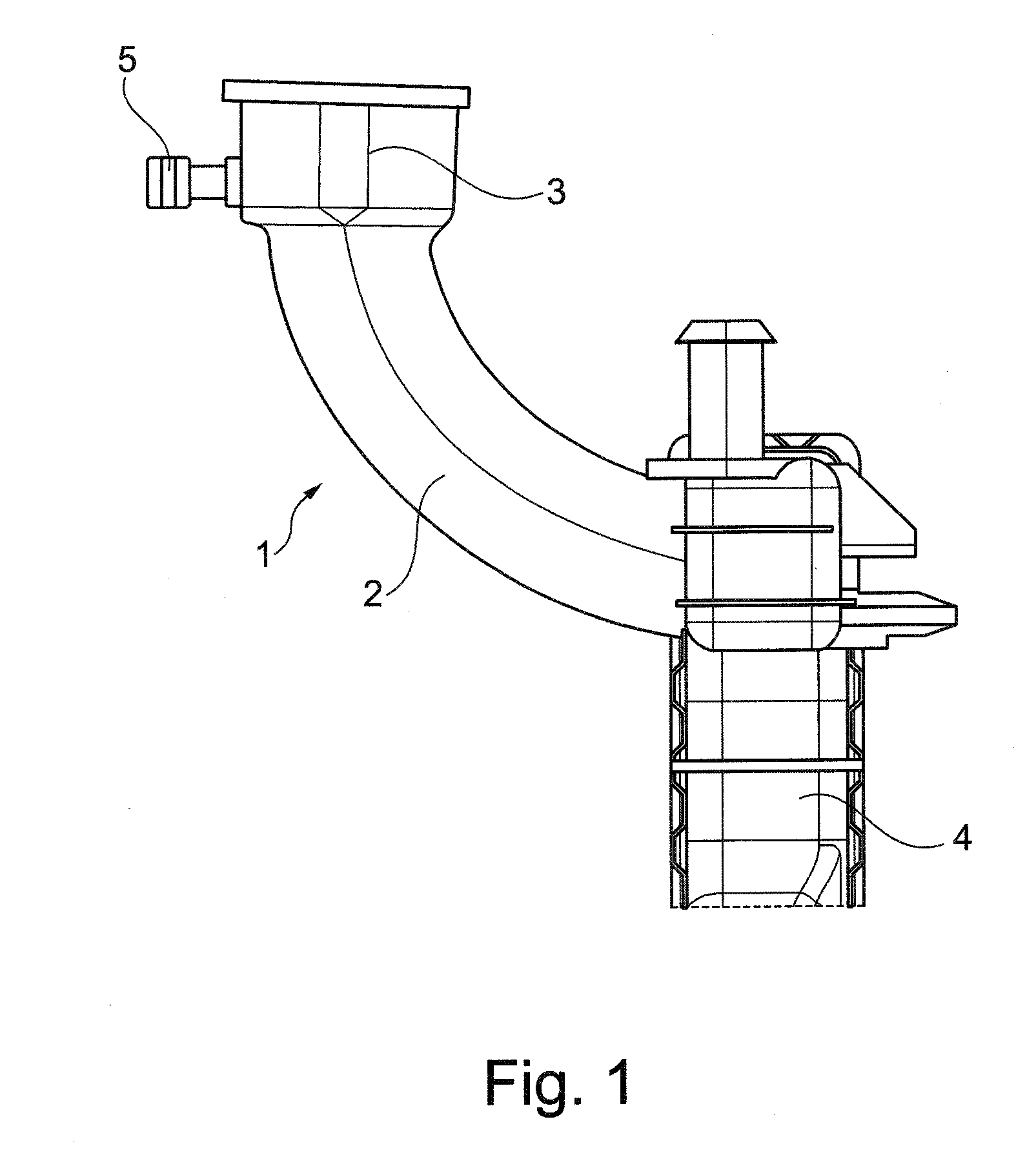
[0016]The figure shows a first embodiment of the filler neck 1 according to the invention. Such a filler neck 1 is used by filling a fluid system with fluid. Such fluid systems are especially radiator assemblies or engine coolant systems, which are filled with a coolant.

[0017]The filler neck 1 includes a filler tube 2 and a filler beginning 3. The filler tube 2 is arranged on the fluid system 4 wherein the filler tube 2 is curved. Hence, the filler beginning 3, which is designed at the filler tube 2 opponent to the fluid system 4, is directed perpendicularly to an opening of the fluid system 4 not depicted in addition. Laterally, a flanged socket 5 extends to the filler beginning 3. The diameter of the filler beginning 3 is larger as the diameter of the filler tube 2.

[0018]The whole filler neck 1 comprises the filler tube 2, the filler beginning 3 and the flanged socket 5 and is fabricated as one piece. Advantageously, the filler neck is formed of plastic material. The filler neck 1...


PUM

PropertyMeasurementUnit
diameteraaaaaaaaaa
outer diameteraaaaaaaaaa
radius of curvatureaaaaaaaaaa

Abstract

A filler neck for filling a fluid system, especially for filling a radiator assembly or an engine coolant system is provided. The filler neck avoids breaking of joints and waiving of leak tests by a filler tube and a filler beginning connected with the filler tube.

Description

BACKGROUND OF THE INVENTION[0001]1. Field of the Invention[0002]The invention refers to a filler neck for filling a fluid system, especially for filling a radiator assembly or an engine coolant system.[0003]2. Description of the Background Art[0004]After fabrication of radiator assemblies or engine coolant systems a cooling fluid is brought into the radiator assembly or the engine coolant system. Hence, a filler neck is necessary to fill the fluid into the radiator assembly or the engine coolant system. The filler neck is arranged in an opening of the radiator assembly or the engine coolant system. The filler neck comprises a spin welded cap or a plug to seal an end of port for cantilevered filler necks.[0005]Spin weld of caps or plugs to seal end of port require secondary operation for leak tests. Additionally, a high risk exists of debris from spin welding process of caps. The debris can cause breaking off from joint which can lead to an engine or water pump damage.SUMMARY OF THE ...

Claims


Application Information

Patent Timeline
Patent Type & Authority Applications(United States)
IPC IPC(8): B65B3/04
CPCF01P11/0204
Inventor CALHOUN, THOMASEBERLE, KIPFORSYTH, DAVIDOBRADOVICH, RICHARD
Owner BEHR AMERICA
Why Eureka
Try Eureka