Thermostat housing for a thermostat of an engine cooling arrangement

a technology of thermostat and engine, which is applied in the direction of machines/engines, process and machine control, instruments, etc., can solve the problems of not revealing any provision, and none of the above mentioned prior art documents disclose any provision for achieving coolant flow restriction, so as to improve the controllability of engine coolant flow and reduce co2 emissions

Inactive Publication Date: 2016-07-21
MAHINDRA & MAHINDRA LTD
View PDF3 Cites 2 Cited by
  • Summary
  • Abstract
  • Description
  • Claims
  • Application Information

AI Technical Summary

Benefits of technology

[0012]An object of the present disclosure is to provide thermostat housing for use in a cooling arrangement that facilitate sufficient contact between the coolant and the thermostat by enhancing coolant flow over the thermostat, thereby improving accuracy of the thermostat in detecting coolant temperature.
[0013]Another object of the present disclosure is to provide thermostat housing for use in a cooling arrangement that facilitates sufficient contact between the coolant and the thermostat, thereby resulting in efficient operation of the engine cooling system.
[0014]Still another object of the present disclosure is to provide thermostat housing that improves coolant flow path around the thermostat, thereby enhancing the accuracy of the thermostat which shall help to avoid the overheating of engine components, thereby leading to improved reliability.
[0015]Yet another object of the present disclosure is to provide thermostat housing that provides better controllability of the engine coolant flow and engine coolant temperature, thereby permitting engine operation even at higher coolant temperatures and resulting in less CO2 emissions.SUMMARY
[0016]A sensor housing is disclosed in accordance with an embodiment of the present disclosure. The sensor housing includes a body, at least one receiver, at least one fluid flow director member, at least one fluid retainer member. The body defines an enclosure that receives fluid. The at least one receiver is configured on the body and receives and holds at least one sensor that determines at least one pre-determined property associated with fluid directed thereto as the fluid comes in contact with the at least one sensor. The at least one fluid flow director member is configured on at least one internal wall of the enclosure and defines flow path of the fluid through the enclosure so as to direct the fluid to the at least one sensor and facilitate sufficient contact between fluid and the at least one sensor to ensure precise sensing of the at least one pre-determined property associated with the fluid by the at least one sensor.
[0017]In accordance with another embodiment of the present disclosure a housing for a thermostat of a cooling arrangement for an engine of a vehicle is disclosed. The housing includes a body, a receiver cavity, at least one fluid flow director member and at least one fluid retainer member. The body defines an enclosure that receives coolant fluid of the cooling arrangement after the coolant fluid has extracted heat from the engine. The enclosure is in fluid communication with a pump that pumps the coolant fluid to a sink of the cooling arrangement for dissipating heat extracted by the coolant fluid from the engine. The receiver cavity is configured on the body and receives and holds the thermostat that determines temperature of coolant fluid directed thereto as the coolant fluid comes in contact with the thermostat. The at least one fluid flow director member is configured on at least one internal wall of the enclosure and defines flow path of the coolant fluid through the enclosure so as to direct coolant fluid to the thermostat and facilitate sufficient contact between coolant fluid and the thermostat to ensure precise sensing of temperature of coolant fluid by the thermostat. The at least one fluid retainer member is configured on the body and is disposed around the thermostat and prevents the coolant fluid from directly reaching suction of the pump by bypassing of the thermostat, thereby retaining the coolant fluid in contact with the thermostat for a pre-determined time to ensure precise sensing of temperature of coolant fluid by the thermostat. Typically, the at least one sensor is selected from a group consisting of pH sensor, concentration sensor and temperature sensor.

Problems solved by technology

However, none of the above mentioned prior art documents disclose any provision for profiling the flow-paths of the thermostat housing for modifying flow-path line of the coolant for facilitating sufficient contact between the coolant and the thermostat.
Further, none of the above mentioned prior art documents disclose any provision for achieving coolant flow restriction for facilitating sufficient contact between the coolant and the thermostat.

Method used


Image

  • Thermostat housing for a thermostat of an engine cooling arrangement
  • Thermostat housing for a thermostat of an engine cooling arrangement
  • Thermostat housing for a thermostat of an engine cooling arrangement

Examples


Embodiment Construction

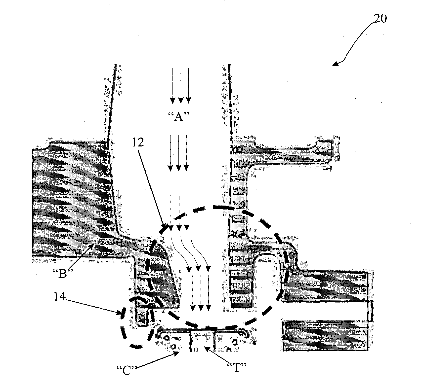
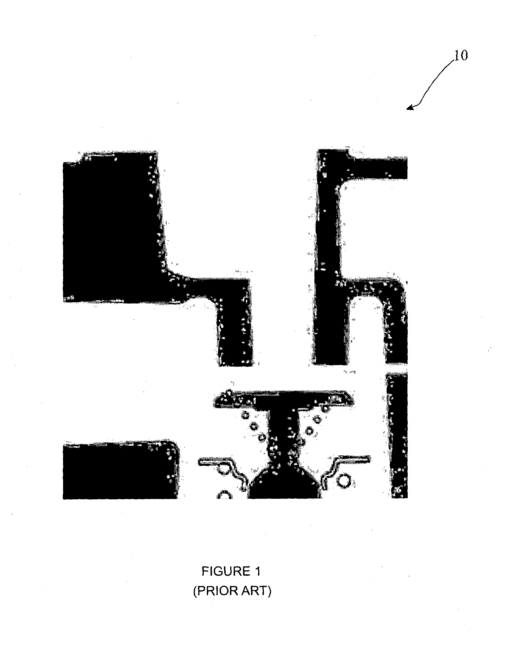
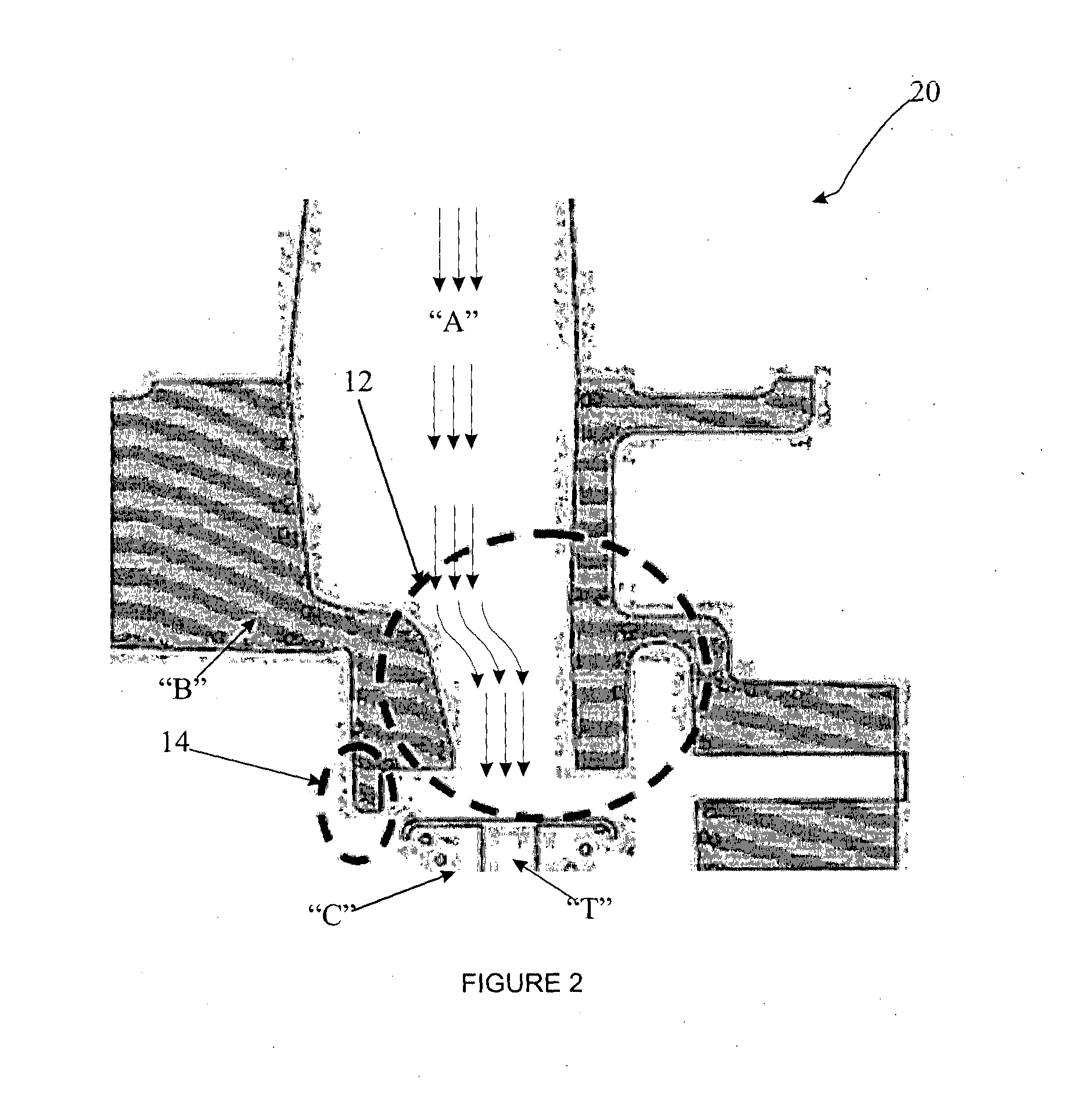
[0029]The disclosure will now be described with reference to the accompanying drawings which do not limit the scope and ambit of the disclosure. The description provided is purely by way of example and illustration.

[0030]The embodiments herein and the various features and advantageous details thereof are explained with reference to the non-limiting embodiments in the following description. Descriptions of well-known components and processing techniques are omitted so as to not unnecessarily obscure the embodiments herein. The examples used herein are intended merely to facilitate an understanding of ways in which the embodiments herein may be practiced and to further enable those of skill in the art to practice the embodiments herein. Accordingly, the examples should not be construed as limiting the scope of the embodiments herein.

[0031]The foregoing description of the specific embodiments will so fully reveal the general nature of the embodiments herein that others can, by applying...


PUM


Abstract

A housing for a thermostat includes a body, a cavity, at least one director member and at least one retainer member. The body defines an enclosure that receives coolant fluid. The enclosure is in fluid communication with a pump that pumps the coolant fluid to a sink for dissipating heat extracted by the coolant fluid. The cavity configured on body receives and holds thermostat that determines temperature of coolant fluid. The director member is configured on at least one internal wall of the enclosure and defines flow path of the coolant fluid so as to direct coolant fluid to thermostat and facilitate sufficient contact between coolant fluid and thermostat and the retainer member configured on the body is disposed around thermostat to prevent the coolant fluid from bypassing of the thermostat, thereby retaining coolant fluid in contact with thermostat to ensure precise sensing of temperature by the thermostat.

Description

FIELD OF DISCLOSURE[0001]The present disclosure relates to a cooling arrangement. More particularly, the present disclosure relates to thermostat housing for a thermostat used for detecting temperature of engine coolant used in an engine cooling arrangement.BACKGROUND[0002]An engine cooling system includes a coolant flow passage formed around a cylinder block of an engine for extracting heat generated in the engine during operation of the engine. The heated coolant is then circulated to a radiator with the help of a pump for dissipating the extracted heat, wherein the heated coolant is cooled down by air-flow and the cooled coolant is circulated back to the coolant flow passage to repeat the cycle of heat extraction from the engine. The flow of engine coolant to the radiator is governed based on temperature of the engine coolant detected by a thermostat. The thermostat should accurately detect the temperature of the engine coolant and allow or by-pass coolant flow to the radiator. C...

Claims


Application Information

Patent Timeline
Patent Type & Authority Applications(United States)
IPC IPC(8): F01P7/16
CPCF01P7/16G05D23/022
Inventor BOITA, DHANANJAYA RAOGHARE, PRAFULLA PRAKASHVENKATACHALAM, KARTHIKEYANSWAROOP, PARTHPRADEEP, MOHANKUMARPANDIYAN, SENTHURVELUSAMY, RAMASAMY
Owner MAHINDRA & MAHINDRA LTD
Why Eureka
Try Eureka