Disc milling cutter and a kit comprising such a disc milling cutter

Pending Publication Date: 2020-02-20
SANDVIK INTELLECTUAL PROPERTY AB
View PDF3 Cites 2 Cited by
  • Summary
  • Abstract
  • Description
  • Claims
  • Application Information

AI Technical Summary

Benefits of technology

[0019]According to another embodiment of the invention the kit further comprises locking means for securing the at least one disc milling cutter and the at least one spacer ring on the shaft of the rotatable tool holder, the locking means comprising a lid being mountable to an end of the shaft by an attachment member clamping the lid onto the spacer ring or the first or second axially directed side abutment surface of the disc milling cutter in the securing state of the locking means, wherein the lid comprises a coolant connection for communicating coolant between a central coolant channel mouthing at the end of the shaft and the axial through-hole(s) in the spacer ring or the disc milling cutter in contact with the lid. The provision of the kit with such a locking means enables the use of a standard tool holder for the use of the at least one disc milling cutter of the kit for metal cutting machining whil

Problems solved by technology

However, such external cooling/flushing is inefficient.
In particular, flushing with a coolant/flushing fluid for purpose of flushing away/chips by means of one or more external coolant/flushing fluid jets directed towards the disc milling cutter and the work piece from the outside will be very ineffective as most of the coolant/flushing fluid will not reach the machining area (inside a machined slot/groove) where it could be used for flushing away/evacuating the chips.
In case of a liquid coolant this inefficient cooling/flushing will also result in a formation of a large amount of waste liquid, which has to be

Method used


Image

  • Disc milling cutter and a kit comprising such a disc milling cutter
  • Disc milling cutter and a kit comprising such a disc milling cutter
  • Disc milling cutter and a kit comprising such a disc milling cutter

Examples


Example

[0032]A milling tool 1 according to a first embodiment of the invention suitable for slot milling as well as face milling and shoulder milling and also for so called gang milling, which will be explained further below when making reference to FIG. 4, will now be described while making reference simultaneously to FIGS. 1-3. The milling tool has a rotatable tool holder 2 to be rotary preventing attached to a milling machine and having a shaft 3 with a member 4 for rotary preventing attachment of at least one spacer ring 5 and at least one disc milling cutter 6 according to the present invention by corresponding cut outs 7, 8 therein. The thickness of a disc milling cutter may be any but may typically vary from 2 mm to 26 mm and mostly from 6 mm to 26 mm resulting in corresponding slot widths when used for slot milling. The diameter of the disc milling cutter is for example 60 mm-320 mm.

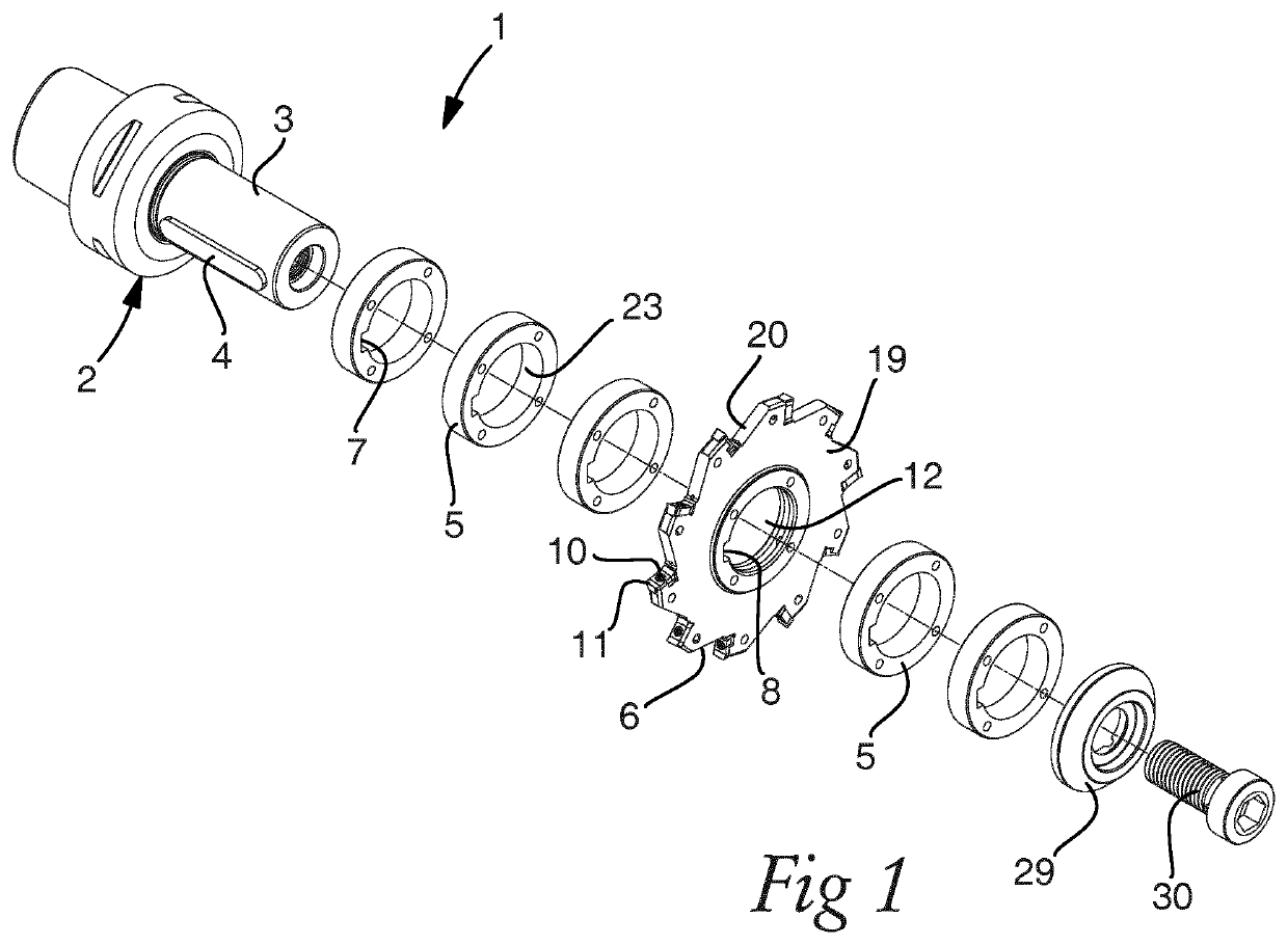
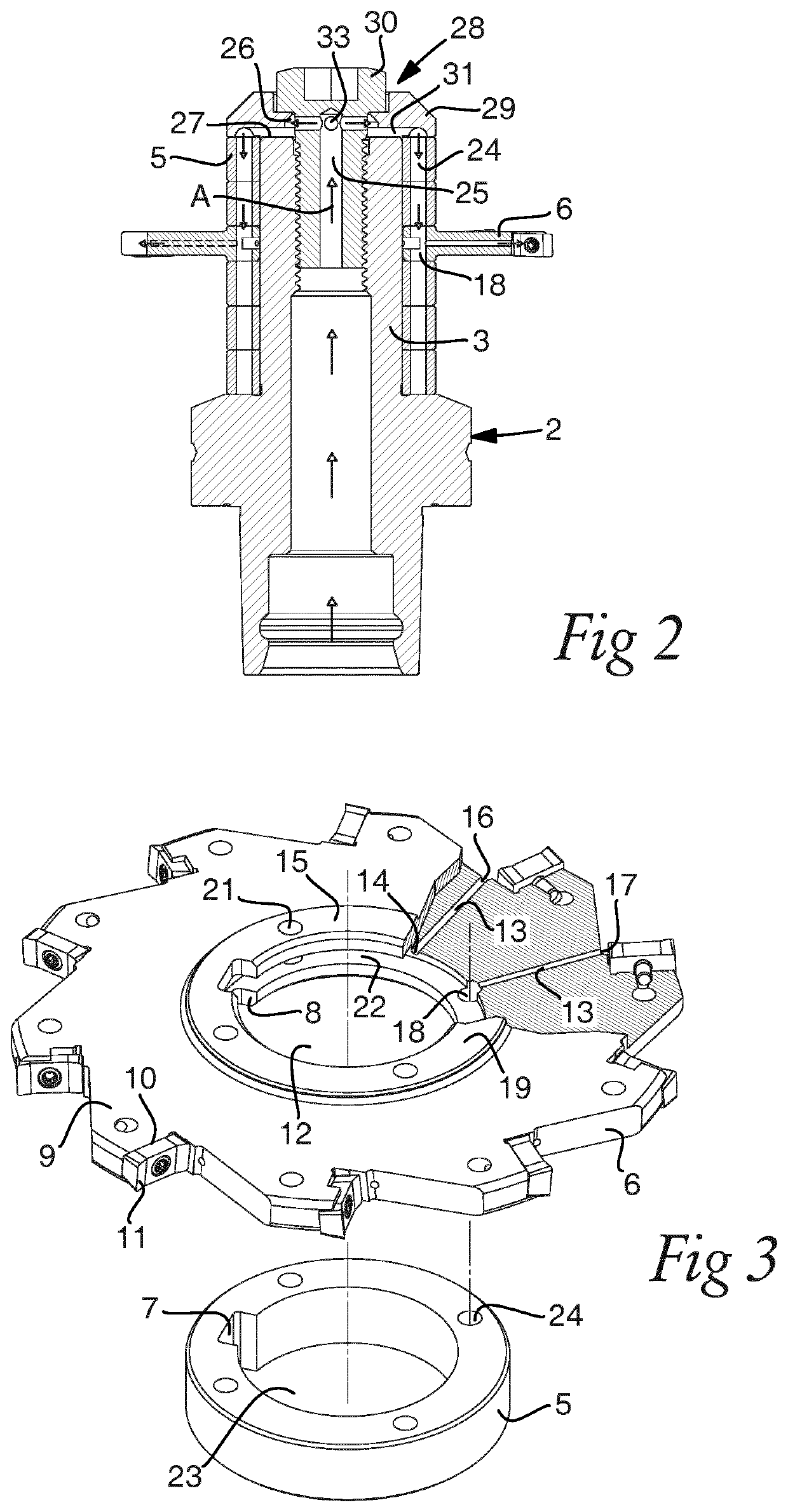
[0033]The design of a disc milling cutter 6 according to a first embodiment of the invention mainly ...

Example

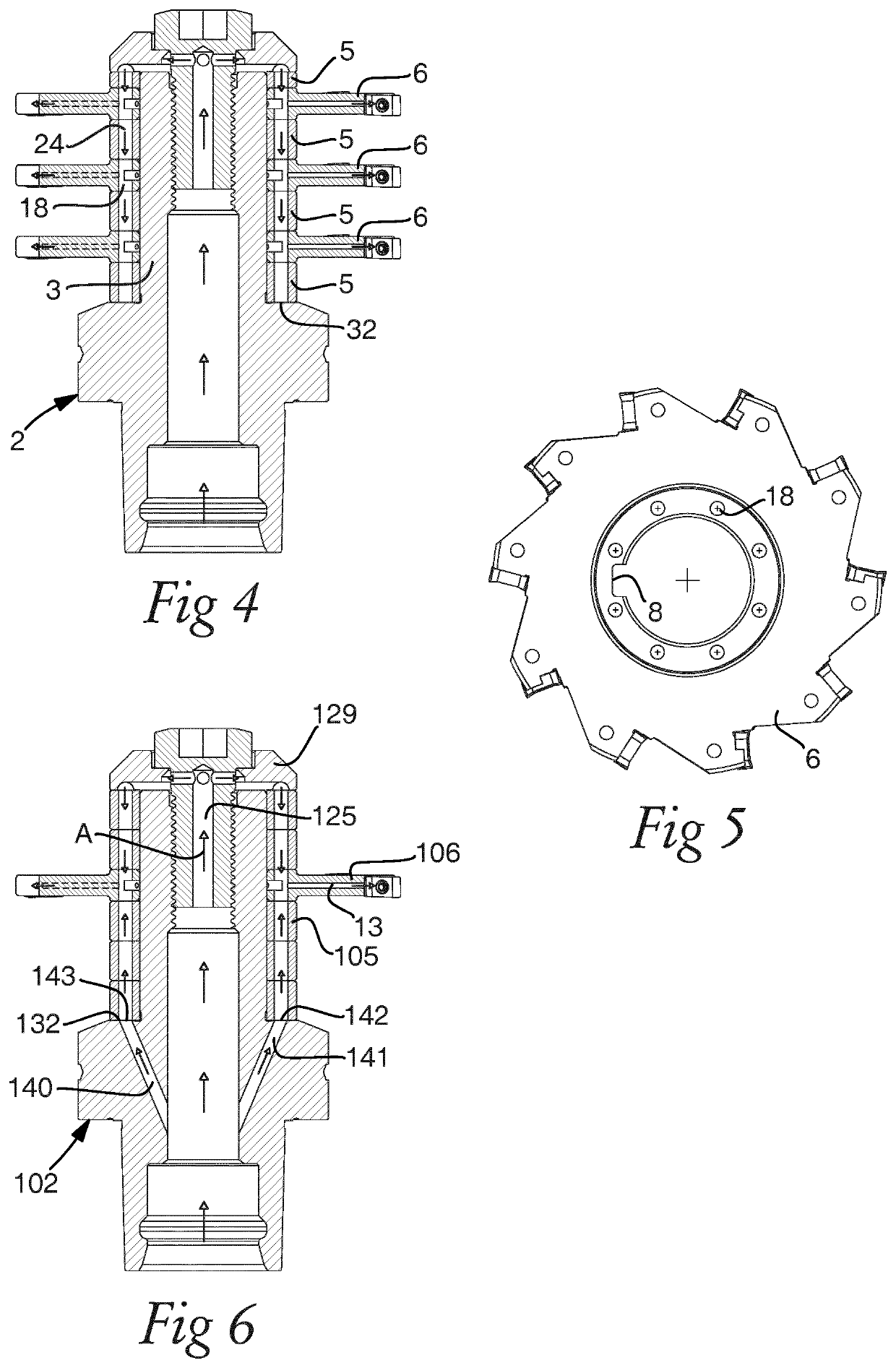
[0040]FIG. 6 illustrates a kit according to a third embodiment of the invention in an operative state differing from the kit shown in FIG. 2 by the design of the tool holder 102. The tool holder is provided with additional coolant channels 140, 141 emerging from the central coolant channel 125 and ending in a respective feed opening 142, 143 in the mounting surface of the collar 132. Each feed opening is positioned to provide feeding of coolant from the coolant channel thereof to one axially directed inlet opening in an axially directed side abutment surface of the disc milling cutter 106 through an axial through-hole of the spacer rings 105 mounted on the tool holder shaft 103 between the collar 132 and the disc milling cutter 106. The number of such additional channels 140, 141 inside the tool holder is preferably, but not necessarily, at least as high as the number of the axial through-holes in the disc milling cutter. In the embodiment shown in FIG. 6 it is possible to provide f...


PUM


Abstract

A milling tool for metal cutting machining has a tool holder with a shaft. At least one disc milling cutter having a central through-hole is mounted on the shaft. The disc milling cutter has internal coolant channels extending radially therein and connected to a coolant source through axial through-holes aligned with axial through-holes of one or more spacer rings, which are also mounted on the shaft, so as to provide for feeding of coolant to the disc milling cutter when placed in different positions along the extension of the shaft.

Description

TECHNICAL FIELD OF THE INVENTION[0001]The present invention relates to a disc milling cutter according to the preamble of appended claim 1 and a kit comprising such a disc milling cutter.[0002]The invention relates to disc milling cutters of different designs, such as disc milling cutters designed purely for slot milling or disc milling cutters also designed for side and face milling. The invention is however particularly useful in so called gang milling having a plurality of disc milling cutters mounted to the same shaft.[0003]When milling a metal work piece by means of a rotating disc milling cutter, it is often advantageous or even necessary to flush the work piece and / or the disc milling cutter with a coolant / flushing fluid in the form of a gas or a liquid or a mixture of gas and liquid. Hence, such cooling / flushing can be performed for different reasons, e.g. for cooling and / or lubricating purpose or for flushing away / evacuating chips from the work piece during machining. Accor...

Claims


Application Information

Patent Timeline
IPC IPC(8): B23C5/28B23C5/08
CPCB23C5/28B23C2250/12B23C2210/244B23C5/08Y02P70/10B23C5/283
Inventor LEHTO, RALF
Owner SANDVIK INTELLECTUAL PROPERTY AB
Why Eureka
Try Eureka