
Hardware write-protection

Active Publication Date: 2013-07-25
QUIXANT
View PDF2 Cites 1 Cited by
  • Summary
  • Abstract
  • Description
  • Claims
  • Application Information

AI Technical Summary

Benefits of technology

The patent text describes a system that allows for secure write-protection of memory devices. This means that the system can prevent unauthorized access to memories, even if they have some electrical write-protection. The system can be used in computer systems where secure write-protection is necessary. The technical effect of the system is to provide a means for secure memory devices and to protect against unauthorized access.

Problems solved by technology

Such memory devices can be regarded as being partially hardware write-protected, but not fully secure in all circumstances.
These devices typically include an electrical write-protect signal, but the write-protect function is further dependent on the programming of internal register bits, rendering the memory device not fully compliant to the requirement for absolute electrical control over the write / erase cycles.
The fact that software can modify settings that change the write-protection status of the memory data renders such memory devices unusable in certain secure applications.

Method used


Image

  • Hardware write-protection
  • Hardware write-protection
  • Hardware write-protection

Examples


Embodiment Construction

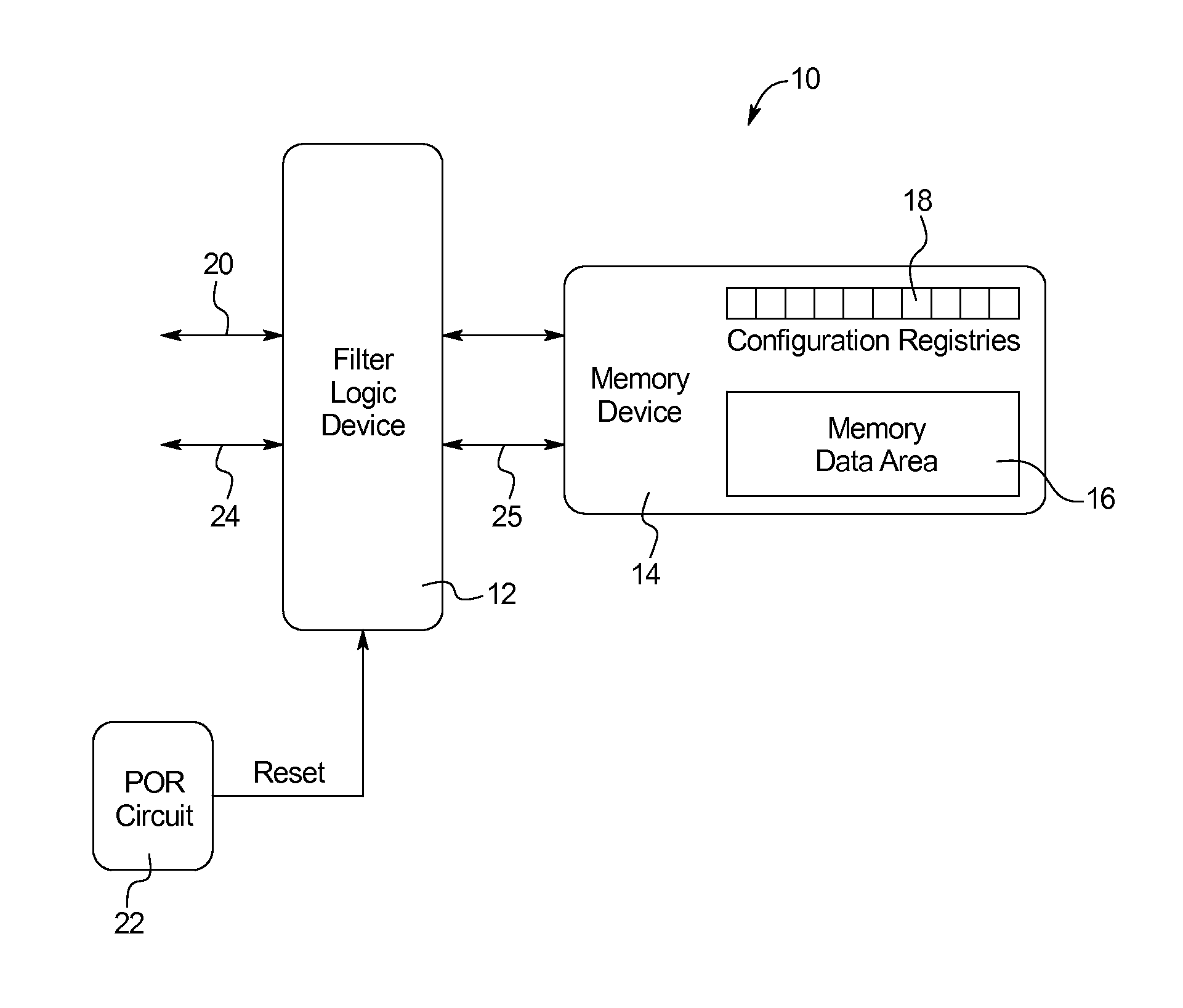
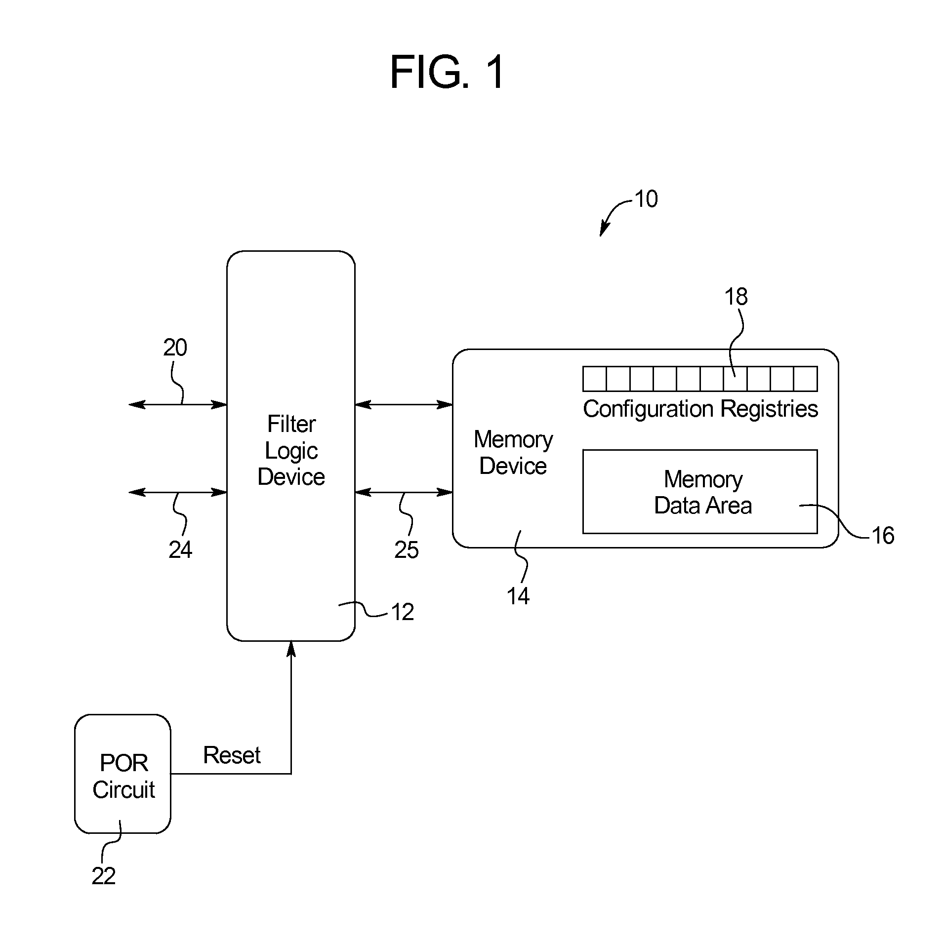
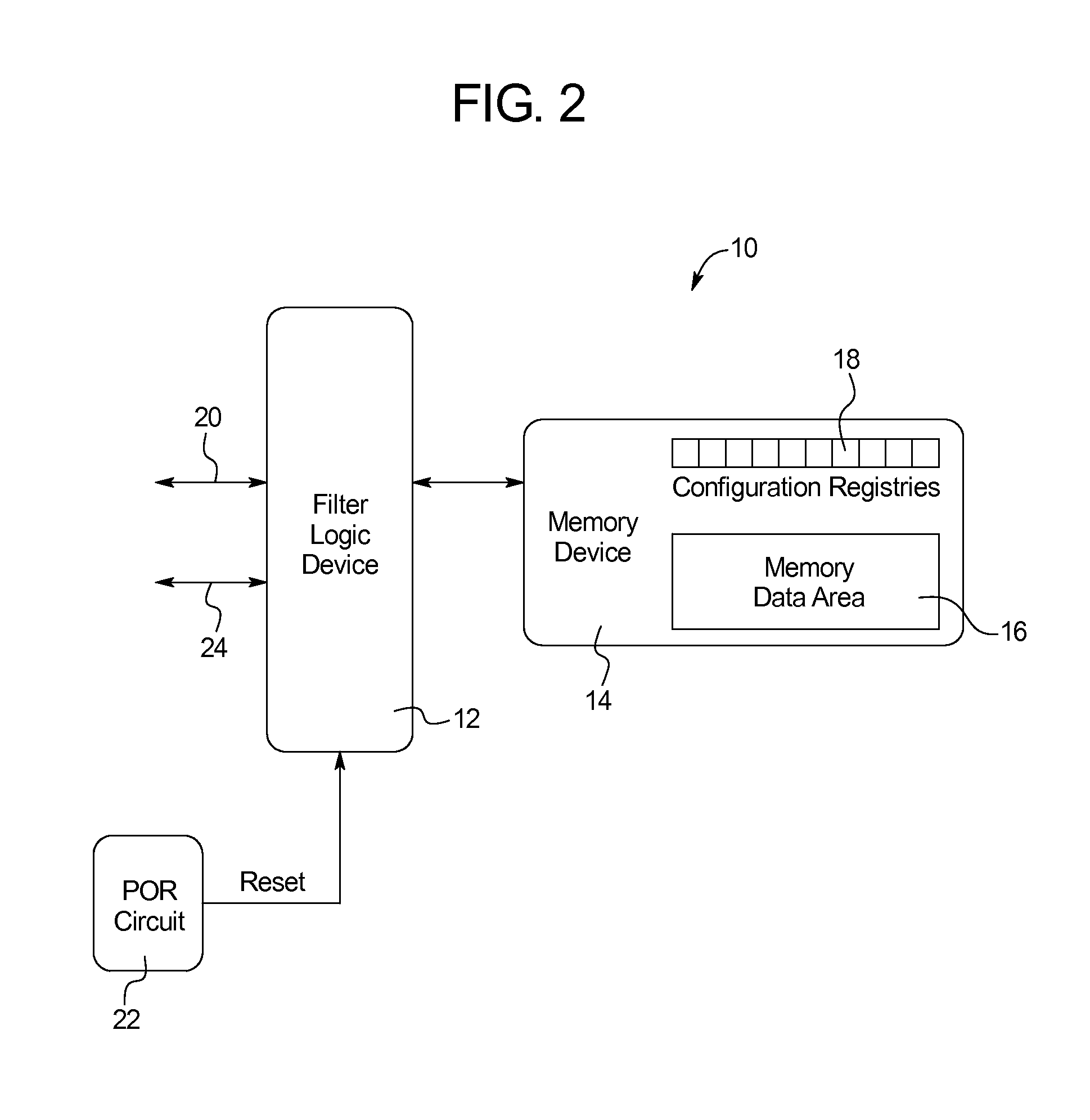
[0034]FIG. 1 illustrates an example of an embodiment of a system for providing electrical control of write and erase operations in memory devices 10 (system 10). As shown in FIG. 1, the system 10 includes: a filter logic device 12; a memory device 14 including a memory data area 16 and one or more configurable registers 18; a system interface 20; and a power on reset (POR) circuit 22. As will be described in further detail, the filter logic device 12 is responsible for providing secured write-protection functionality to the memory device 14.

[0035]The system 10 shown in FIG. 1 is adapted for use in a slot machine operating using standard PC architecture. However, it is understood that the disclosures provided herein will enable those skilled in the art to implement the system 10 within various microprocessor controlled systems to provide write-protection functionality to memory devices 14. Accordingly, while the examples provided herein are provided in the context of use in a slot ma...


PUM


Abstract

A system for providing write-protection functionality to a memory device includes: a memory device including configurable registers controlling write and erase operations in the memory device; a system interface; a filter logic device in electrical communication with the memory device and further in communication with the system interface; and a power on reset circuit in communication with the system interface and the filter logic device, wherein the power on reset circuit asserts a reset signal to the system interface on startup of the system, further wherein, while the reset signal is asserted to the system interface, the filter logic device modifies the configurable registers to prevent all further write and erase operations to the memory device and then the power on reset circuit de-asserts the reset signal to the system interface enabling communication between the system interface and the memory device.

Description

CROSS-REFERENCE TO RELATED APPLICATIONS[0001]This application incorporates by reference and claims priority to U.S. Provisional Patent Application No. 61 / 588,633 filed Jan. 19, 2012.BACKGROUND OF THE INVENTION[0002]The present subject matter relates generally to systems and methods for securing write and erase operations in a memory device. More specifically, the present subject matter provides systems and methods in which a filter logic device is employed between a memory device and the system in which it is used to filter commands from the system to the memory device.[0003]There are many computer systems in which one or more memory devices are used to store critical information within the computer system. While there are nearly limitless variations of such systems and environments in which they are used, the disclosure provided herein discussed the subject matter in the context of gambling machines. While described in the gambling machine context, it is understood that the teachin...

Claims


Application Information

Patent Timeline
IPC IPC(8): G11C5/14
CPCG11C5/14G06F12/1433G06F9/4401G06F21/575G07F17/3241H04L9/0838
Inventor JARMAY, NICHOLAS CHARLES LEOPOLD
Owner QUIXANT
Learn More