Management device, control method, and program
- Summary
- Abstract
- Description
- Claims
- Application Information
AI Technical Summary
Benefits of technology
Problems solved by technology
Method used
Image
Examples
first embodiment
[0036](Functional Configuration of Management Device 100)
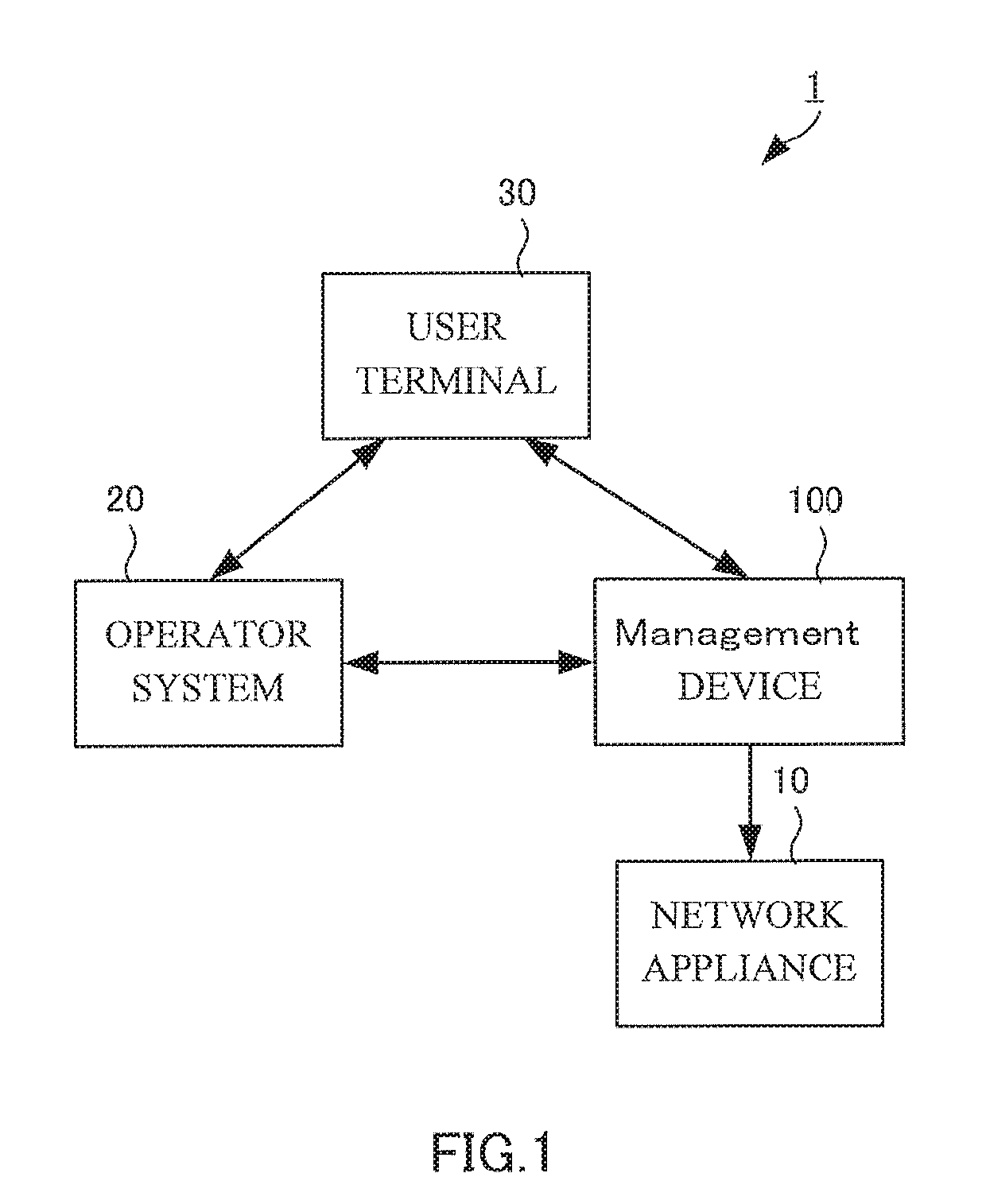
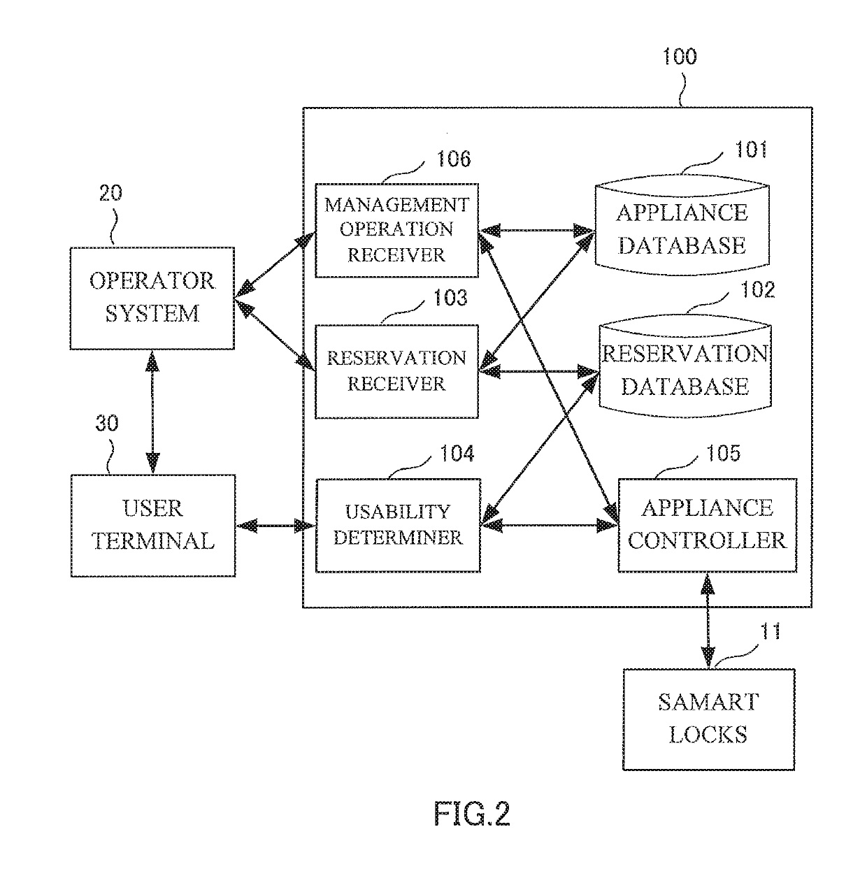
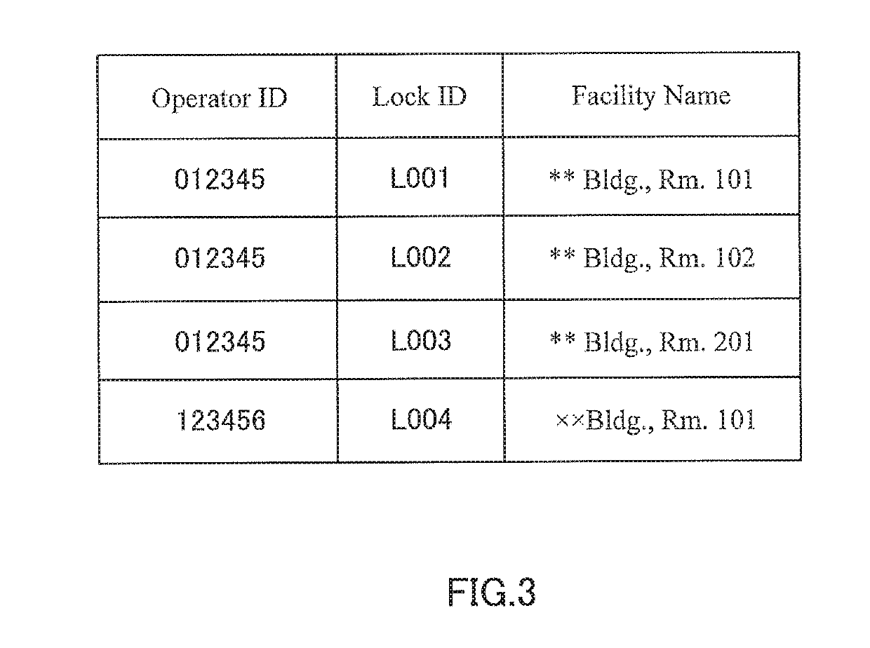
[0037]FIG. 2 is a diagram showing a functional configuration of management device 100 according to a first embodiment of the present invention. Additionally, in the following description, a case where network appliance 10 is smart lock 11 is described. In this example, management device 100 provides a function of managing reservation information regarding a facility where smart lock 11 is installed, and of controlling smart lock 11 based on the reservation information. Operator system 20 uses the function provided by management device 100, and provides a service for enabling a user to use the facility where smart lock 11 is installed for a specific period of time. For example, operator system 20 provides a function of authorizing a user for a specific period of time to open / close smart lock 11, in order to provide a service such as private viewing of real estate, private accommodation, a shared office, a housekeeping service, ...
second embodiment
[0065](Configuration of Management Device 200)
[0066]FIG. 12 is a diagram showing a configuration of management device 200 according to a second embodiment of the present invention. Also in the present embodiment, as in the first embodiment, management device 200 may receive reservation information from operator system 20, and may temporarily provide authorization to operate network appliance 10, based on the reservation information. In the first embodiment, network appliance 10 is smart lock 11, but in the present embodiment, network appliance 10 includes smart lock 11, camera 12, light 13, and smart plug 14. In the following, a difference to the first embodiment will be mainly described, and a description of aspects the same as those of the first embodiment will be omitted.
[0067]Management device 200 includes appliance database 201, reservation database 202, reservation receiver 203, usability determiner 204, appliance controller 205, and management operation receiver 206. For the ...
third embodiment
[0076]Management device 100 according to the first embodiment controls smart lock 11, and management device 200 according to the second embodiment controls network appliances 10 such as camera 12, light 13, and smart plug 14, in addition to smart lock 11. In contrast, management device 300 according to a third embodiment of the present invention is capable of controlling camera 12, instead of smart lock 11. In this case, camera 12 may be installed at any location indoor and outdoor, without being restricted to a facility where smart lock 11 is installed.
[0077]A functional configuration of management device 300 is the same as that described with respect to management device 100 according to the first embodiment, except that smart lock 11 is replaced by camera 12, and a description thereof is omitted.
[0078]
[0079]Examples of the functions of management devices 100, 200, 300 are described above using the first to the third embodiments. Each structural element described above may be conf...
PUM
 Abstract
Description
Claims
Application Information
 - R&D
- Intellectual Property
- Life Sciences
- Materials
- Tech Scout
- Unparalleled Data Quality
- Higher Quality Content
- 60% Fewer Hallucinations
Browse by: Latest US Patents, China's latest patents, Technical Efficacy Thesaurus, Application Domain, Technology Topic, Popular Technical Reports.
© 2025 PatSnap. All rights reserved.Legal|Privacy policy|Modern Slavery Act Transparency Statement|Sitemap|About US| Contact US: help@patsnap.com


