Infinitely adjustable coolant pump

Inactive Publication Date: 2014-01-02
SCHAEFFLER TECH AG & CO KG
View PDF4 Cites 1 Cited by
  • Summary
  • Abstract
  • Description
  • Claims
  • Application Information

AI Technical Summary

Benefits of technology

[0008]To avoid this, the actuation unit may optionally include a spring. This spring applies pressure to the guide plate indirectly via the shaft in the guide-plate-opening direction. This embodiment provides a fail-safe solution. If the actuator fails and the guide plate is pulled by a negative fluid force in the guide-plate-closing direction, thereby reducing the coolant flow, the spring produces a counterpressure to prevent the guide plate from closing. However, in this embodiment, all of the force curves would have to be increased by the preload of the spring. This would partially cancel out the previously achieved force reduction.
[0009]In order to be able to use a conventional inexpensive

Problems solved by technology

For this reason, the actuators used are m

Method used


Image

  • Infinitely adjustable coolant pump
  • Infinitely adjustable coolant pump
  • Infinitely adjustable coolant pump

Examples


Embodiment Construction

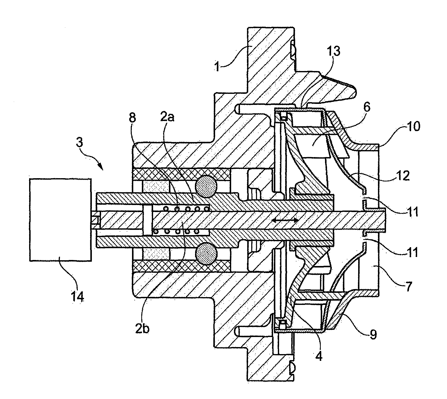
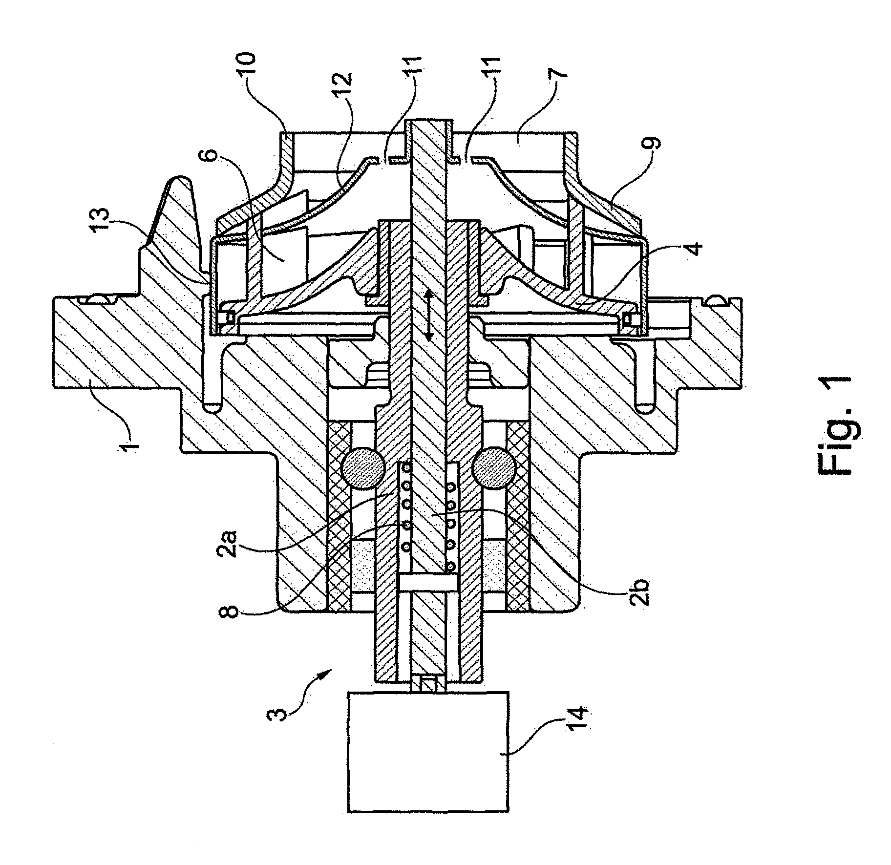
[0022]FIG. 1 shows a coolant pump for a coolant circuit of an internal combustion engine, the coolant pump having a pump housing 1, in which is mounted a drivable shaft 2a having an impeller 4 attached to one end thereof. Impeller 4 has vanes 6 extending into suction chamber 7. Impeller 4 and cover plate 9 are joined to one another. When impeller 4 rotates, fluid is conveyed into suction chamber 7 through an intake port 10 of pump housing 1. A guide plate 12, which is axially displaceable by an actuation unit 3, is disposed between impeller 4 and cover plate 9. Guide plate 12 has a contour corresponding to impeller 4 and a collar 13 oriented toward impeller 4. In order to achieve rapid heating of the internal combustion engine and to selectively adjust the engine temperature, the coolant pump must be controllable or switchable. To this end, a volume flow rate is adjusted in accordance with demand. In order to adjust the volume flow rate, guide plate 12 is axially displaced in pump h...


PUM


Abstract

A coolant pump for a coolant circuit of an internal combustion engine, the coolant pump having a pump housingin which is mounted a drivable shaft, to one end of which is attached an impeller-which has vanes extending into a suction chamber and is connected to a cover plate. Fluid can be drawn into the suction chamber through an intake port of the pump housing by joint rotation of the impeller and the cover plate and can be conveyed by the vanes into the pump housing. A guide plate, which is axially displaceable by an actuation unit, is disposed between the impeller and the cover plate. The guide plate has a contour corresponding to the impeller and a collar oriented toward the impeller. The coolant pump is characterized in that the guide plate has at least one opening.

Description

[0001]The present invention relates to a coolant pump for a coolant circuit of an internal combustion engine. The coolant pump has a pump housing in which is mounted a drivable shaft, to one end of which is attached an impeller which has vanes extending into a suction chamber and is connected to a cover plate. As a result of the rotation of the cover plate and the vaned impeller, fluid is drawn into the suction chamber through an intake port of the pump housing and conveyed further into the pump housing by the vanes. A guide plate, which is axially displaceable by an actuation unit, is disposed between the impeller and the cover plate. The guide plate has a contour corresponding to the impeller and a collar oriented toward the impeller.BACKGROUND[0002]In order to achieve rapid heating of the internal combustion engine and to selectively adjust the engine temperature, the coolant pump should be switchable or ideally controllable. This is accomplished selectively by adjusting the flow...

Claims


Application Information

Patent Timeline
IPC IPC(8): F04D3/00
CPCF04D3/00F04D15/0038
Inventor HURST, SEBASTIANPOPP, MARKUSLUEKEN, CARSTEN
Owner SCHAEFFLER TECH AG & CO KG
Why Eureka
Try Eureka