Material Plate

a technology of material plates and plates, applied in the field of material plates, can solve the problems of unacceptable amount, and achieve the effect of reducing the total amount of unacceptable products and reducing manufacturing deviations

Inactive Publication Date: 2009-09-03
PRICE DAVID ELWYN
View PDF4 Cites 8 Cited by
  • Summary
  • Abstract
  • Description
  • Claims
  • Application Information

AI Technical Summary

Benefits of technology

[0010]It is therefore an object of the invention to provide a material plate, which can be manufactured with a low rate of unacceptable product. It is a further object of the invention to provide a material plate in which either side of the product may be used as the decor side at installation.BRIEF SUMMARY OF THE INVENTION
[0012]The use of identical decor layers on both sides of the substrate advantageously allows the manufacture of floor coverings that can be laid with either one or the other side facing up in order to accommodate for possible faulty pressings. A particular piece that may not be acceptably installed in one orientation, may be acceptably installed in the reverse orientation. This added flexibility decreases the amount of unacceptable and, therefore, unusable, product
[0013]Where the material plates are manufactured with specialty designs, for example special, custom ordered (and often expensive) decor patterns and for which a low threshold of defect is acceptable, the decor pattern applied to the reverse side may be a less expensive, more readily marketable pattern, for example a light beech plank imitation, so that product which is unacceptable for the special, custom ordered application, may be acceptable for use as a mass marketed product. As a rule, the costs for a faulty pressings of specially manufactured material plates are very high, so that it is economical to provide, by way of precaution only, an alternative decor layer on the opposite side in order that, in the event that the special high-quality first decor layer is faulty, some product may still be sold in the mass market because the second lower quality side is acceptable for this purpose. Such faults can, for instance, derive from altering degrees of gloss of the press plates or altering parameters in the manufacture of the material plates. The additional cost to apply an additional decor layer is relatively low, so that even with this increased expense, the cost of faulty pressings can be mitigated. In this manner it is possible to economically and competitively manufacture individual material plates with identical or different patterns either using the first (upper) or second (lower) layer as the visible side at installation. The decor layers used may consist of a film, provided with amino plastic resins, may be a printed decor paper or may be a direct imprint on the substrate plate or any combination of these. The particular layer to be used can, of course, be selected in order for an economical production of the material plates.
[0019]A further embodiment of the invention provides for a glue layer disposed between the substrate and the decor layer on at least one side. The glue layer provides additional strength to the connection between the decor layer and the substrate layer.
[0024]The invention thus provides material plates, which may be applied, for example, as a floor covering, and in which the material plates are manufactured with a nearly identical sequence of layers to both sides of the substrate layer in order that manufacturing deviations are diminished. Additionally the material plates may be installed in either orientation. Where the material plates are manufactured with two different decor layers on opposite sides, for example, one decor layer acceptable for high quality flooring and the opposite decor layer acceptable in the mass market, product which is not acceptable for the high quality flooring application may, nevertheless, be suitable for the lower quality application. In this way, the total amount of unacceptable product is diminished.

Problems solved by technology

This added flexibility decreases the amount of unacceptable and, therefore, unusable, product
Such faults can, for instance, derive from altering degrees of gloss of the press plates or altering parameters in the manufacture of the material plates.

Method used


Image

  • Material Plate
  • Material Plate

Examples


Embodiment Construction

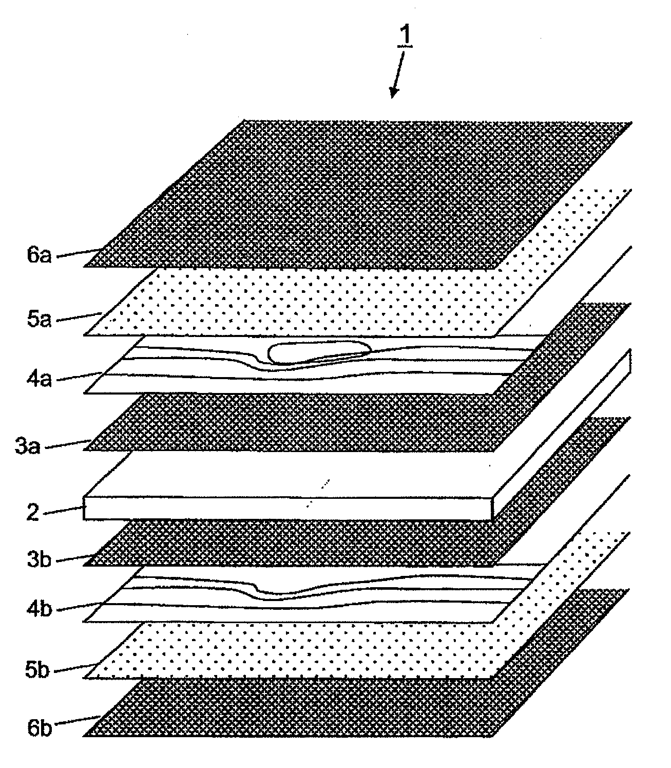
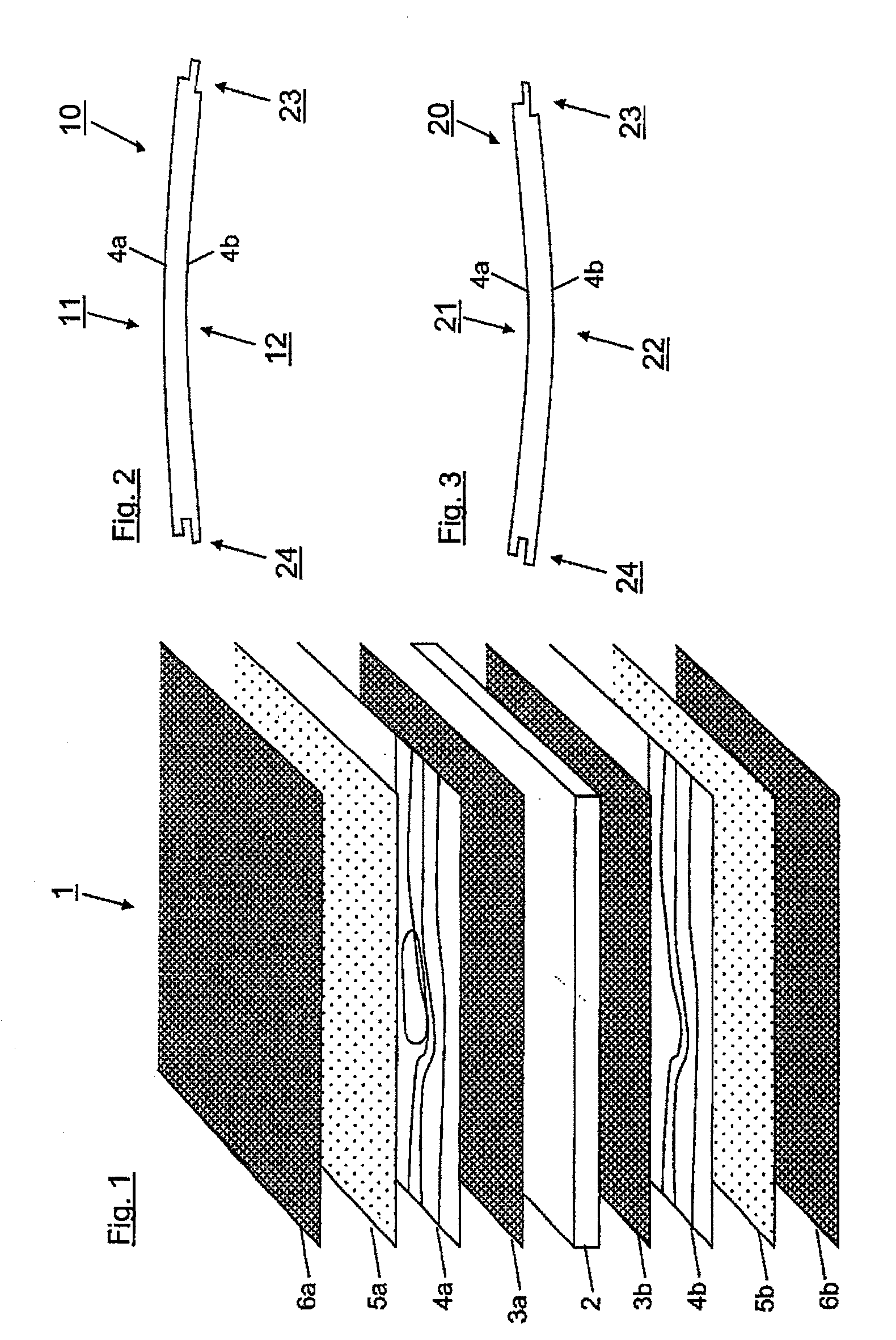
[0029]In FIG. 1 the sequence of layers of a material plate 1 according to the invention is shown. Here, a central substrate layer 2, comprised of medium density fibreboard, oriented strand board, particle board, high density fibreboard, or plywood, is covered on both sides with a glue-adhesive layer, 3a, 3b. The glue-adhesive layer may be an adhesive film. The glue-adhesive layer 3a, 3b, shown in the embodiment is not required for the invention, and is only used in particular cases during production. A sequence of layers reduced by the glue-adhesive layer 3a, 3b may also be employed. A decor layer 4a, 4b comprised of, for example, a paper of low grammage and imprinted decor is disposed over the glue-adhesive layers 3a, 3b. In prior art it is common to apply a decor layer only on one side of the substrate layer 2, and to apply a counteracting paper of non-decorative recycled paper on the back of the substrate layer. According to the invention, however, a decor layer 4a, 4b is provide...


PUM

PropertyMeasurementUnit
abrasion resistantaaaaaaaaaa
transparentaaaaaaaaaa
densityaaaaaaaaaa

Abstract

A material plate suitable for use as a floor covering comprises a middle substrate layer having two sides and a first and second decor layer on each side of the substrate. The decor layers may be advantageously different in aesthetic appearance. A transparent overlay layer is provided over the one and preferably both decor layers. Either the decor layers or the overlay layers, or both, comprise abrasion-resistant particles to extend wear.

Description

RELATED APPLICATIONS[0001]This application claims priority from and incorporates by reference, German utility model application DE 20 2007 008 360.2.BACKGROUND OF THE INVENTION[0002]1. Field of the Invention[0003]The invention relates to a material plate, in particular a material plate to be used as floor covering, comprising at least one middle substrate layer (carrier plate) and a decor layer on at least a first side of the substrate layer.[0004]2. Introduction[0005]The manufacture of material plates that are to be used as floor covering is accomplished by using substrates which are frequently made from a fibrous material and which are coated with a defined sequence of paper or nonwoven layers, the individual layers being impregnated with an amino resin, e.g. melamine formaldehyde resin, and cured in a press. During pressing under heat and pressure, the composition is cured to an amino resin layer and connects the individual layers with the substrate layer, so that a very stable a...

Claims


Application Information

Patent Timeline
Patent Type & Authority Applications(United States)
IPC IPC(8): D06N7/00B32B7/12B32B5/16D06N7/04
CPCB32B27/04B44C5/043B44C5/0476E04F15/02Y10T428/24364Y10T428/24372Y10T428/24124Y10T428/24099Y10T428/24066
Inventor PRICE, DAVID ELWYN
Owner PRICE DAVID ELWYN
Why Eureka
Try Eureka