Bracket for Orthodontic

Inactive Publication Date: 2009-09-03
SUYAMA HAJIME
View PDF4 Cites 25 Cited by
  • Summary
  • Abstract
  • Description
  • Claims
  • Application Information

AI Technical Summary

Benefits of technology

[0012](2) Because it is not necessary to make the wings thin, even with a cosmetic br

Problems solved by technology

In the above-mentioned configuration wherein engagement claws are provided on both sides of a tie wing, the production process is complicated, th

Method used


Image

  • Bracket for Orthodontic
  • Bracket for Orthodontic
  • Bracket for Orthodontic

Examples


Example

[0020]An embodiment of the present invention will be explained based on the examples shown in the drawings.

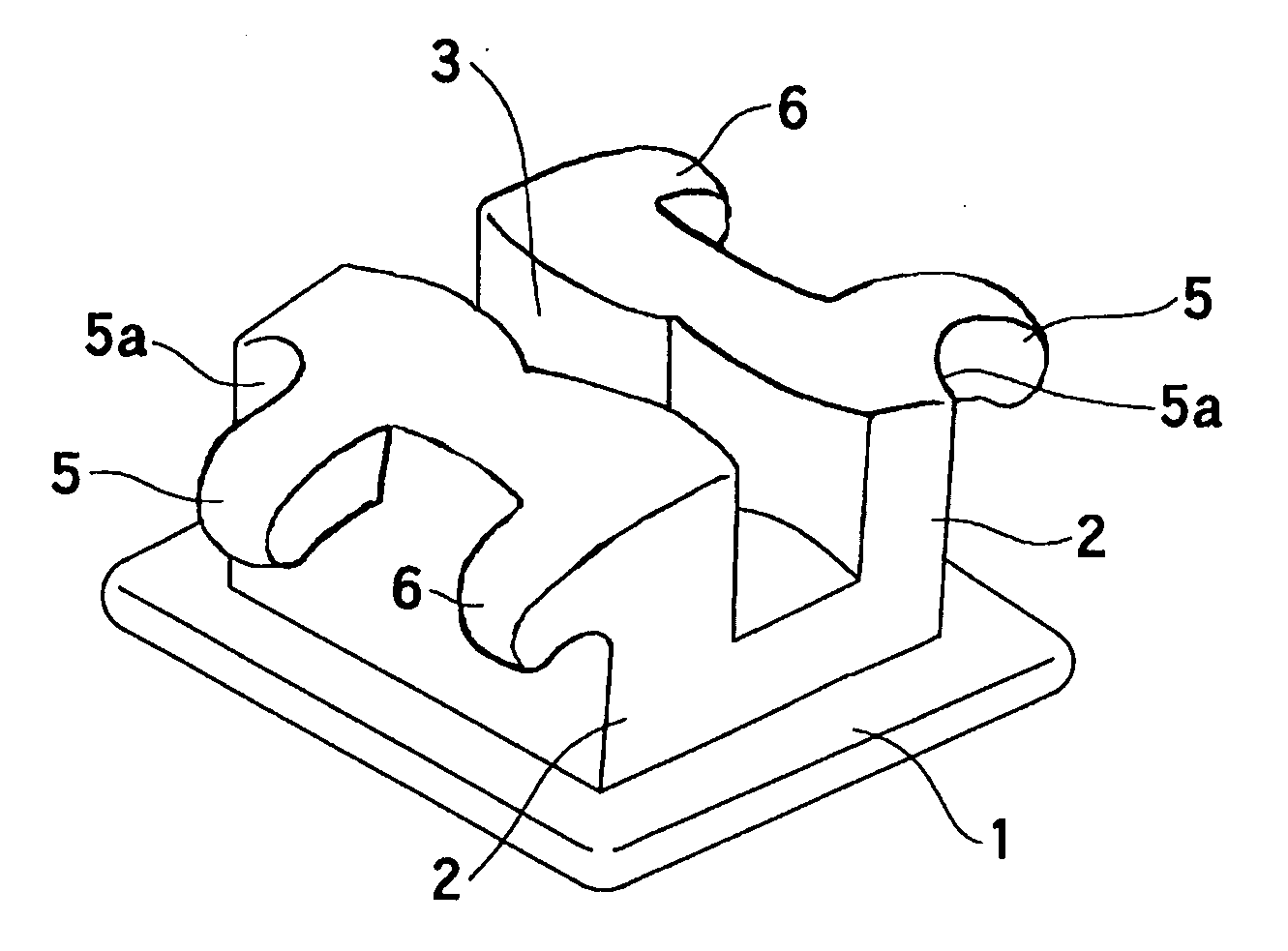
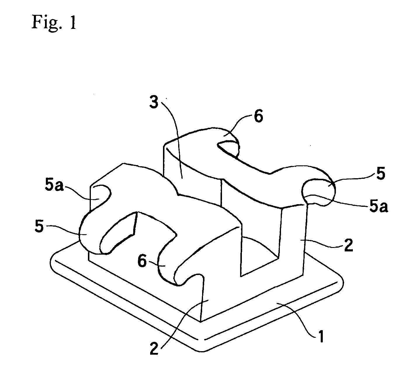
[0021]Referring to FIGS. 1 to 3, an orthodontic bracket according to the present invention is integrally made of stainless steel, a synthetic resin, ceramic or the like and comprises primarily a base plate (1), a tie wing (2) and an arch wire fitting slot (3). More specifically, as shown in FIG. 1, the orthodontic bracket is configured such that a pair of tie wings (2) having a pair of long and short wing pieces, that is, a long piece (5) and a short piece (6), are erected on the rectangular base plate (1) spaced apart from each other, and the arch wire fitting slot (3) is formed by this spaced apart portion.

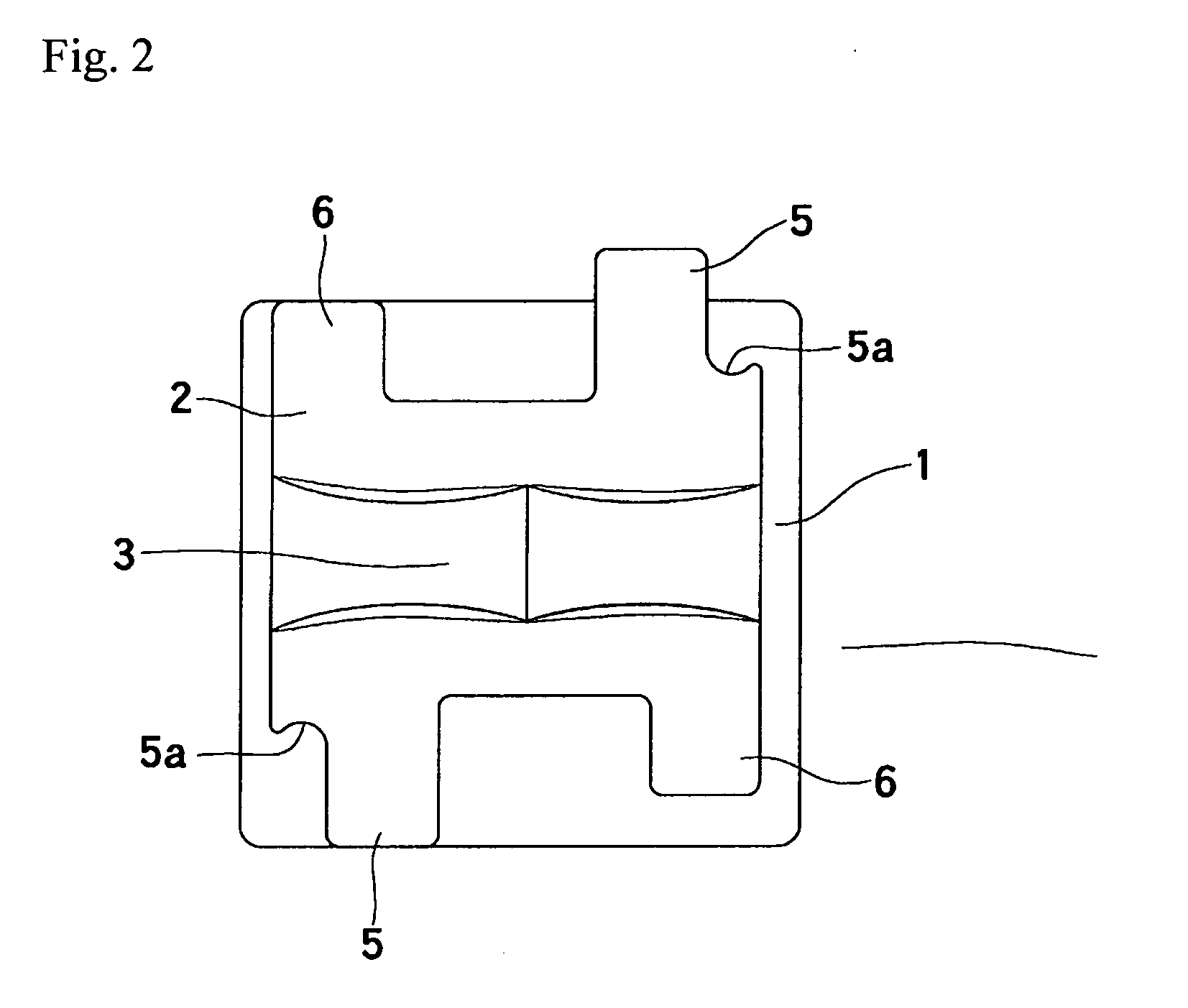
[0022]The pair of wing pieces (5, 6) of the tie wing (2) are provided so as to project in the vertical direction, with the distal ends slanting downwardly, and, as shown in FIG. 2, are constituted by the long piece (5) and the short piece (6). A recessed guide groove (5a) i...


PUM


Abstract

A bracket for orthodontic use has a base plate, a tie wing and an arch wire fitting slot. More specifically, a pair of tie wings having a pair of long and short wing pieces, i.e., a long piece and a short piece, are erected on the rectangular base plate and spaced apart, and the arch wire fitting slot is formed by the spaced apart portion. A pair of wing pieces of the tie wing are provided to project in the vertical direction with distal ends directed downward, and constituted the wing pieces include a long piece and a short piece. A recessed guide groove is provided in a vicinity of an end of the long piece.

Description

BACKGROUND[0001]The present invention relates to a bracket used in orthodontic treatment.[0002]In general, in the first half of orthodontic treatment, because it is necessary to slide an orthodontic bracket along a main wire in order to move teeth, it is better if the resistance between the main wire and the orthodontic bracket is small. On the other hand, in the second half of treatment, because the aligned teeth must be fixed, it is desirable to have large resistance between the main wire and the orthodontic bracket.[0003]Conventional orthodontic brackets comprise a slot for fitting and joining an arch wire or other main wire and a tie wing for catching a ligature wire (or a rubber ring) which fastens and fixes the main wire. In the early stages of treatment (crowded dentition), teeth are moved by the main wire, which is thinner than the width of the slot, using a coil spring and rubber. As the treatment progresses, the main wire is replaced with a thicker one to increase the resi...

Claims


Application Information

Patent Timeline
IPC IPC(8): A61C7/14
CPCA61C7/12A61C7/28A61C7/14
Inventor SUYAMA, HAJIME
Owner SUYAMA HAJIME
Why Eureka
Try Eureka