Variable vane actuation system

a technology of variable speed stator and actuator, which is applied in the direction of cranks, machines/engines, liquid fuel engines, etc., can solve the problems of compressor stalling or surg

Active Publication Date: 2009-09-10
ROLLS ROYCE CORP
View PDF22 Cites 35 Cited by
  • Summary
  • Abstract
  • Description
  • Claims
  • Application Information

AI Technical Summary

Problems solved by technology

However, on the other hand, a higher pressure r

Method used


Image

  • Variable vane actuation system
  • Variable vane actuation system
  • Variable vane actuation system

Examples


example 1

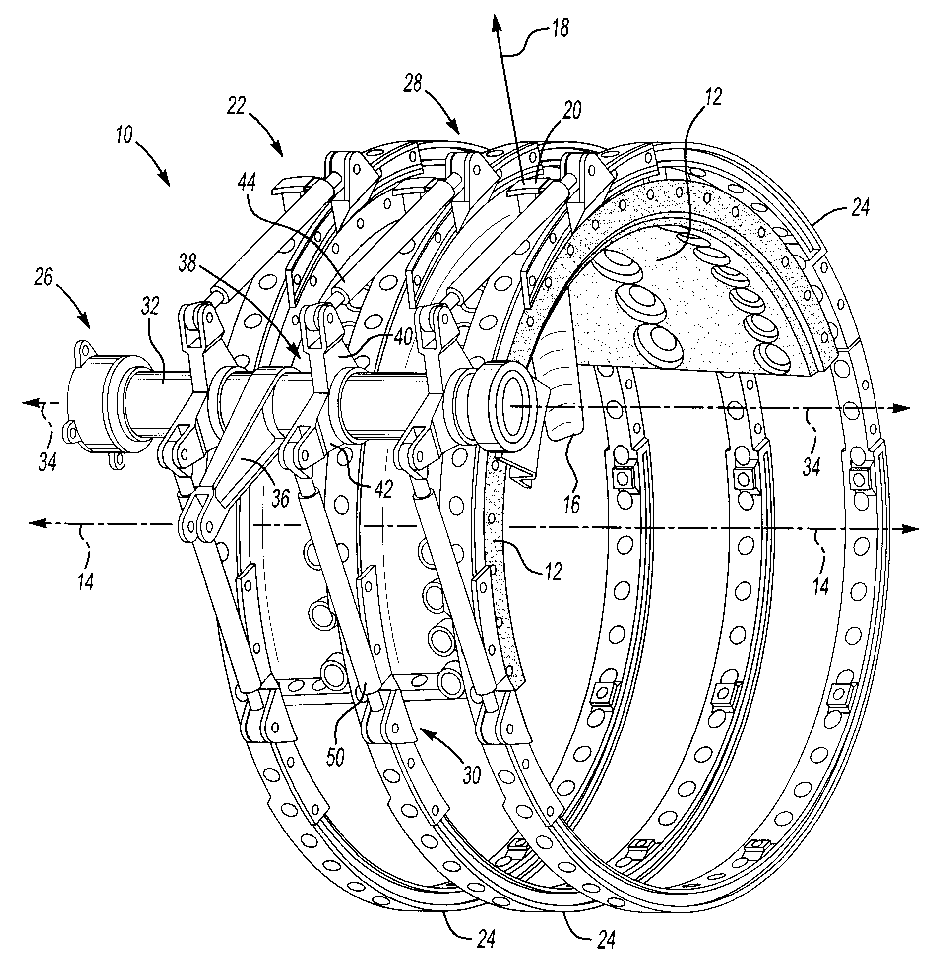
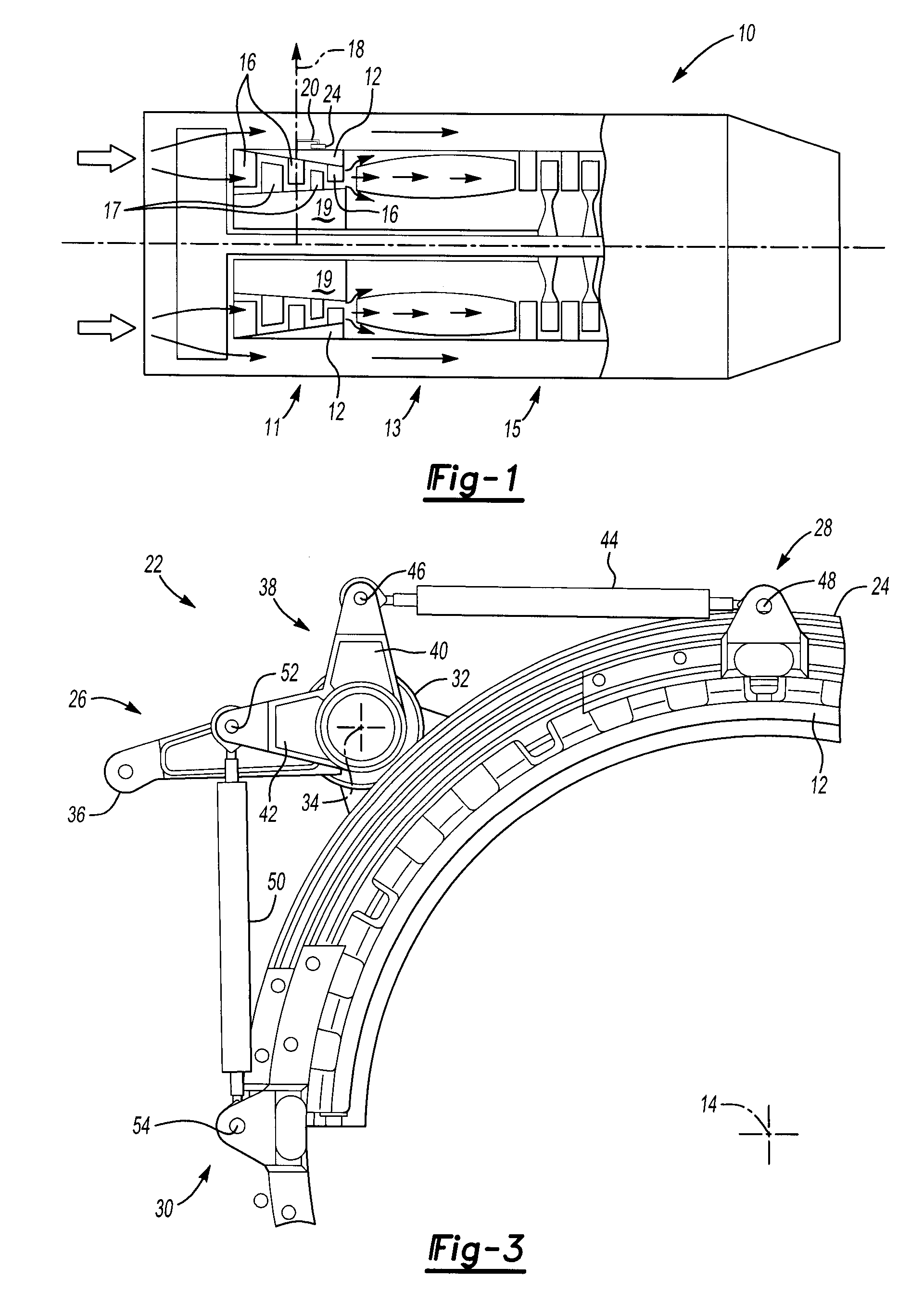
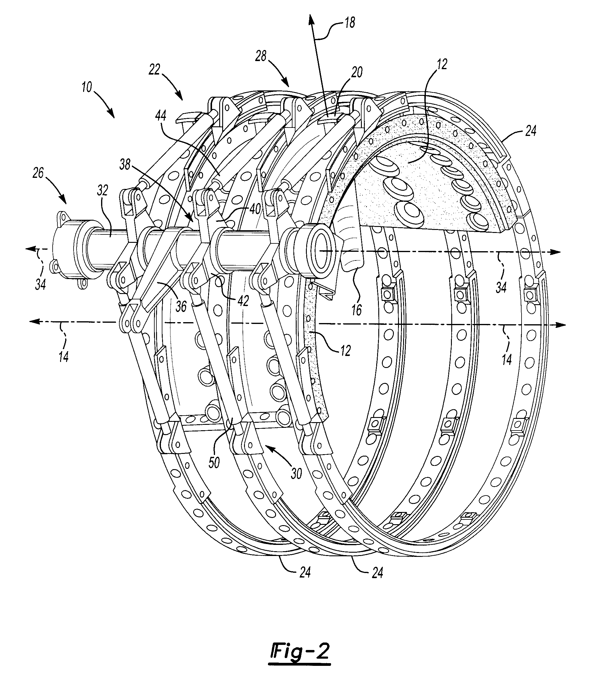
[0024]Many different kinematic relationships can be applied for practicing the broad invention. In one example for practicing the exemplary embodiment of the broader invention, the distance between the centerline axis 14 and the torque tube axis 34 can be 272.5 mm. The distance between the centerline axis 14 and the axis 48 (point of engagement between the first link 44 and the first mounting position 28 of the ring member 24) can be 256.6 mm. The distance between the centerline axis 14 and the axis 54 (point of engagement between the second link 50 and the second mounting position 30 of the ring member 24) can also be 256.6 mm. The distance between the tube axis 34 and the axis 46 (point of engagement between the first link 44 and the arm 40 of the clevis 38) can be 60.15 mm. The distance between the tube axis 34 and the axis 52 (point of engagement between the second link 50 and the arm 42 of the clevis 38) can also be 60.15 mm. The length of the first link 44 (the distance betwee...


PUM


Abstract

A variable vane actuation system is disclosed herein. The variable vane actuation system includes a ring member disposed for pivoting movement about a centerline axis. The ring member is engaged with a plurality of vanes in a turbine engine such that the plurality of vanes pivot in response to the pivoting movement of the ring member. The variable vane actuation system also includes a ring moving device engaged with the ring member at first and second positions spaced from one another about the centerline axis. The ring moving device is operable to apply first and second forces, respectively, at the first and second positions to pivot the ring member.

Description

BACKGROUND OF THE INVENTION[0001]1. Field of the Invention[0002]The invention relates to a system for moving variable stator vanes, such as in a turbine engine for example.[0003]2. Description of Related Prior Art[0004]Variable pitch stator vanes can be used in the compressor sections of gas turbine engines. These vanes can be pivotally mounted inside a compressor case of the turbine engine and can be arranged in circumferential rows that are spaced from one another along a centerline axis of the turbine engine. Each row corresponds to a different stage of the compressor section. Generally, each of the individual vanes can pivot on a spindle about an axis that extends transverse to the centerline axis. Engine performance and reliability can be enhanced by varying the angle of the vanes at different stages during the operation of the turbine engine. For example, in a turbine engine applied to aircraft propulsion, obtaining greater thrust can require the compressor section to impart a...

Claims


Application Information

Patent Timeline
IPC IPC(8): F01D17/12
CPCF04D29/542F01D17/162F16C2360/23F16C3/10F16C3/22
Inventor WONG, ALBERTPEREZ, LUCASTOMMASONE, ANTHONY F.
Owner ROLLS ROYCE CORP
Why Eureka
Try Eureka