Positioning attachment for a welding torch

a technology of positioning attachment and welding torch, which is applied in the direction of soldering apparatus, manufacturing tools,auxillary welding devices, etc., can solve the problems of poor overall weldments, inexperienced welders often have difficulty establishing the proper torch angle, and uneven welding angl

Inactive Publication Date: 2009-09-17
ILLINOIS TOOL WORKS INC
View PDF6 Cites 71 Cited by
  • Summary
  • Abstract
  • Description
  • Claims
  • Application Information

AI Technical Summary

Problems solved by technology

For instance, an improper torch angle can lead to a spatter, improper penetration, and overall poor weldments.
However, inexperienced welders often have difficulty establishing the proper torch angle and torch to workpiece distance during welding, and such skills may be somewhat difficult to teach.
Furthermore, even experienced wel

Method used


Image

  • Positioning attachment for a welding torch
  • Positioning attachment for a welding torch
  • Positioning attachment for a welding torch

Examples


Embodiment Construction

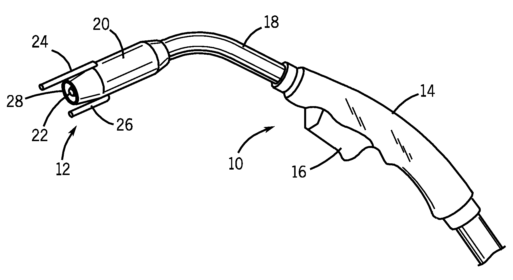
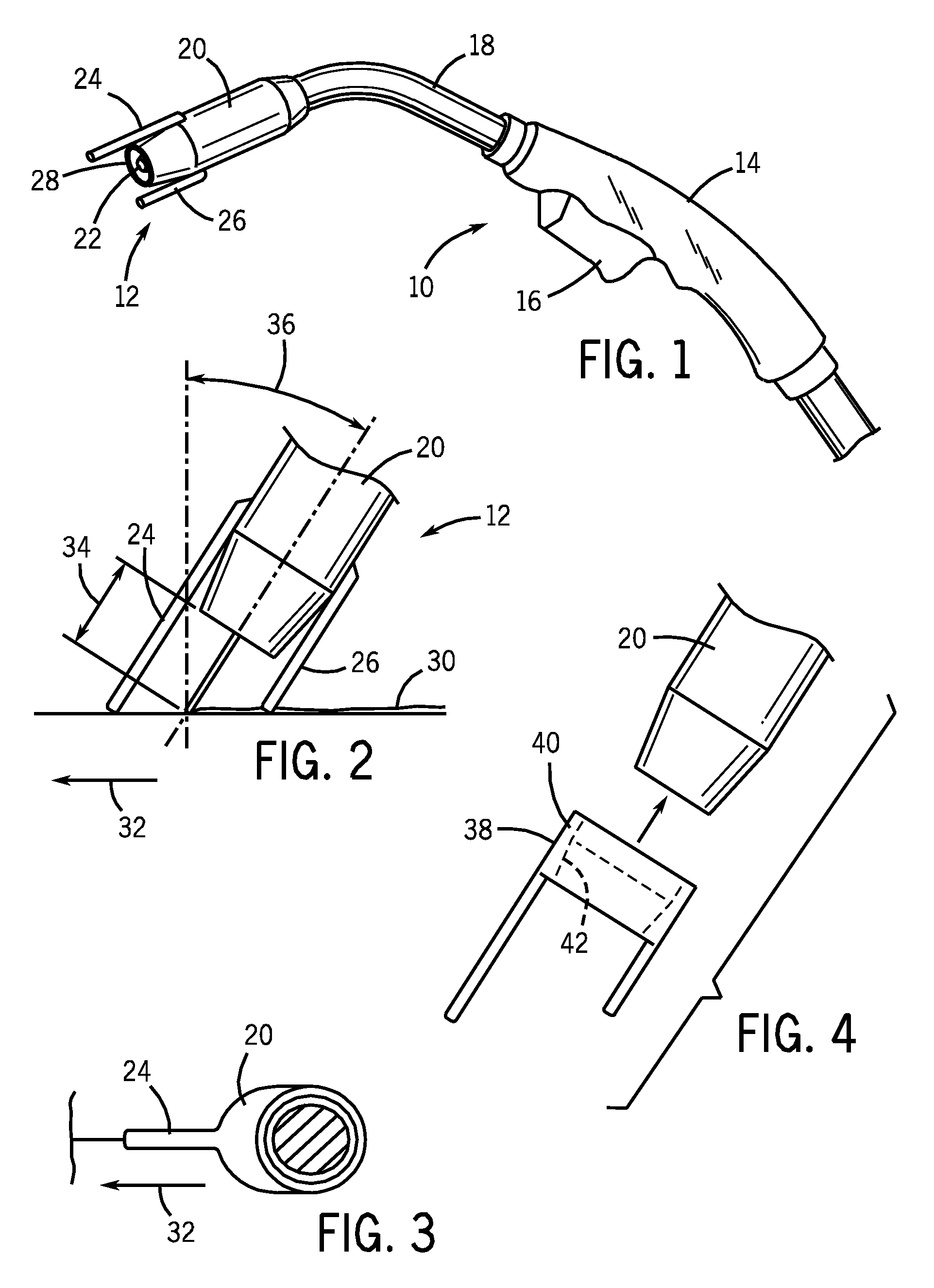
[0021]FIG. 1 illustrates a welding torch 10 that incorporates a positioning attachment 12, which establishes the proper torch angle and / or torch to workpiece height during welding or welding training. The torch 10 has a handle 14 with a trigger 16, which a welder may use to start and stop welding. An extension 18 from the handle 14 is connected to a nozzle 20. A contact tip 22 extends outward from the inner cavity of the nozzle 20. One embodiment of the present invention, which includes two positioning legs 24, 26 permanently attached to the outside of the nozzle on either side of the aperture 28, is shown in FIG. 1. During welding, wire is fed out of the contact tip 22 while gas is fed out of the aperture 28 into the welding area. In certain embodiments, the positioning attachment 12 may be made of a metal, such as brass or steel, which is resistant to the heat generated during welding. In other embodiments, the positioning attachment 12 may be made of ceramic. It should be noted t...


PUM

PropertyMeasurementUnit
Angleaaaaaaaaaa
Lengthaaaaaaaaaa
Electrical resistanceaaaaaaaaaa

Abstract

A positioning attachment for definition of torch angle and torch to workpiece distance during welding and/or training is provided. The positioning attachment includes one or more legs of equal or varied lengths capped with a tip, which contacts the workpiece, and a body, which may be permanently attached or removably secured to the welding torch nozzle. Certain embodiments may be made of heat resistant metals or ceramic to withstand high temperatures during welding. The positioning attachment may be mounted on the welding torch nozzle or provided as an extension of the contact tip.

Description

CROSS REFERENCE TO RELATED APPLICATIONS[0001]This application is a Non-provisional Patent Application of U.S. Provisional Patent Application No. 61 / 036,588, entitled “Training Nozzle / Tip for Welding Applications”, filed Mar. 14, 2008, which is herein incorporated by reference.BACKGROUND[0002]The invention relates generally to welding guns, and more particularly to positioning attachments for controlling torch angle and / or torch to workpiece height during welding.[0003]Welding is a process that has increasingly become ubiquitous in all industries. While such processes may be automated in certain contexts, a large number of applications continue to exist for manual welding operations, the success of which relies heavily on the proper use of a welding gun or torch. For instance, an improper torch angle can lead to a spatter, improper penetration, and overall poor weldments. However, inexperienced welders often have difficulty establishing the proper torch angle and torch to workpiece d...

Claims


Application Information

Patent Timeline
IPC IPC(8): B23K9/32
CPCB23K9/32B23K9/126B23K37/00
Inventor ERTMER, JONATHAN R.
Owner ILLINOIS TOOL WORKS INC
Why Eureka
Try Eureka