Stampable thrust washer with flow cutouts

Active Publication Date: 2009-09-24
SCHAEFFLER TECH AG & CO KG
View PDF20 Cites 8 Cited by
  • Summary
  • Abstract
  • Description
  • Claims
  • Application Information

AI Technical Summary

Benefits of technology

[0014]These and other objects and advantages of the present invention will be readily appreciable from the f

Problems solved by technology

Unfortunately, plastic thrust washers are quite expensive to produce.
However, grooves can not be simply stamped into the steel washers, because this would create protrusions on the face of the washer opposite face from each groove.
Such protr

Method used


Image

  • Stampable thrust washer with flow cutouts
  • Stampable thrust washer with flow cutouts
  • Stampable thrust washer with flow cutouts

Examples


Embodiment Construction

[0029]At the outset, it should be appreciated that like drawing numbers on different drawing views identify identical, or functionally similar, structural elements of the invention. While the present invention is described with respect to what is presently considered to be the preferred aspects, it is to be understood that the invention as claimed is not limited to the disclosed aspects.

[0030]Furthermore, it should be understood that this invention is not limited to the particular methodology, materials and modifications described and as such may, of course, vary. It should also be understood that the terminology used herein is for the purpose of describing particular aspects only, and is not intended to limit the scope of the present invention, which is limited only by the appended claims.

[0031]Unless defined otherwise, all technical and scientific terms used herein have the same meaning as commonly understood to one of ordinary skill in the art to which this invention belongs. Alt...


PUM


Abstract

A stampable thrust washer for a torque converter including an inner circumference, an outer circumference, and a plurality of cutouts disposed in the thrust washer, wherein the cutouts are in fluid communication with the inner and outer circumferences when said thrust washer is engaged between two rotationally engaged components.

Description

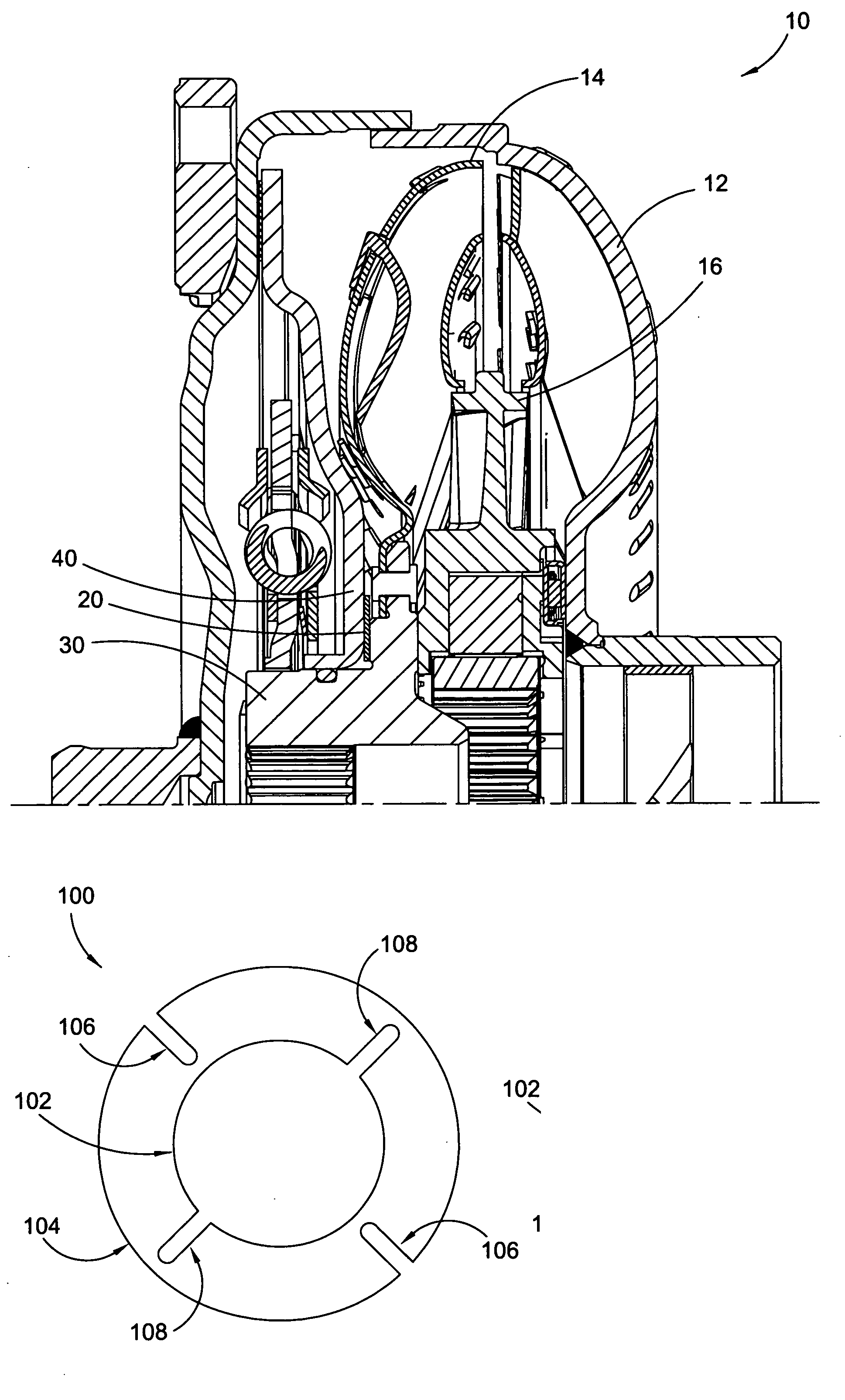
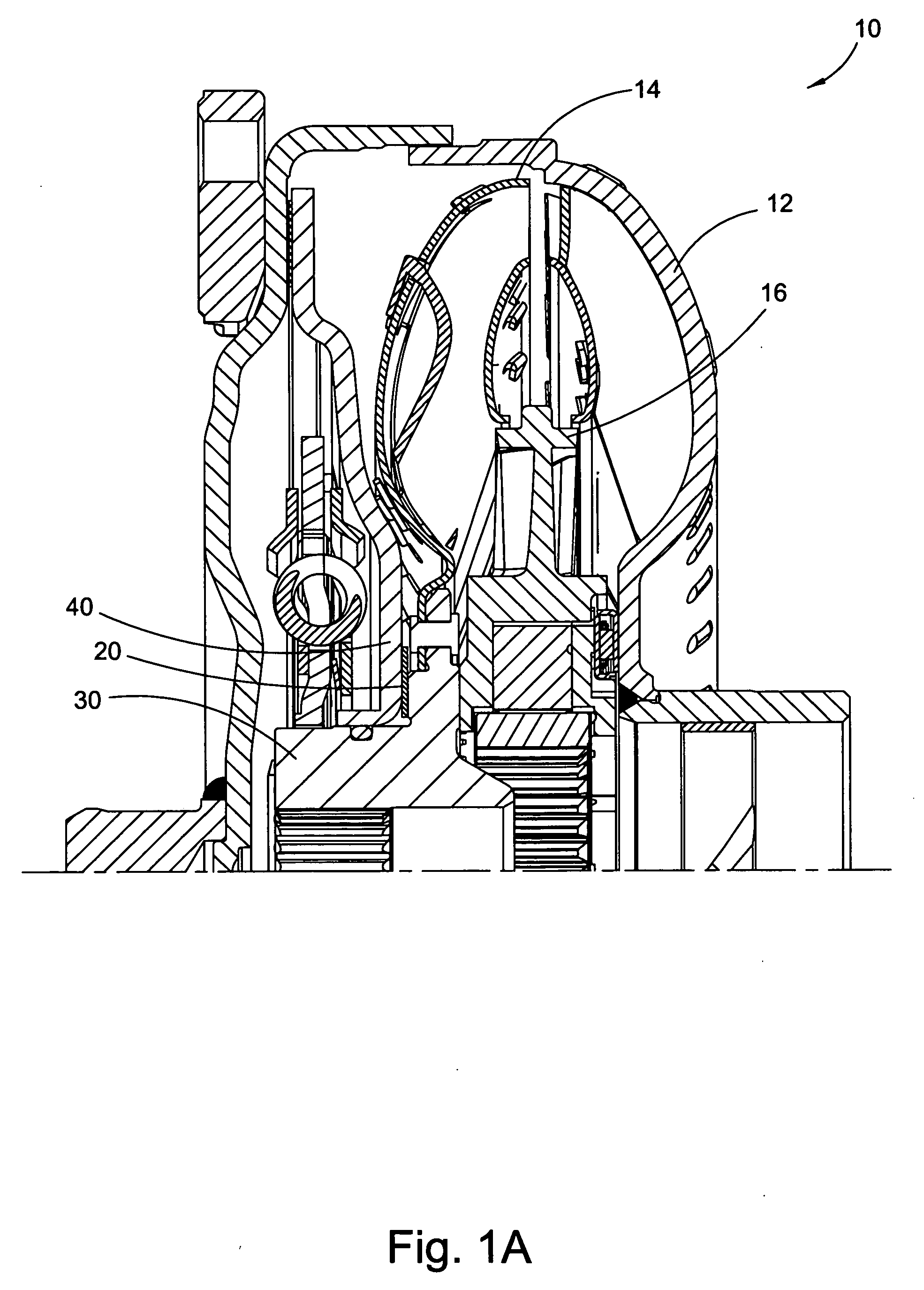
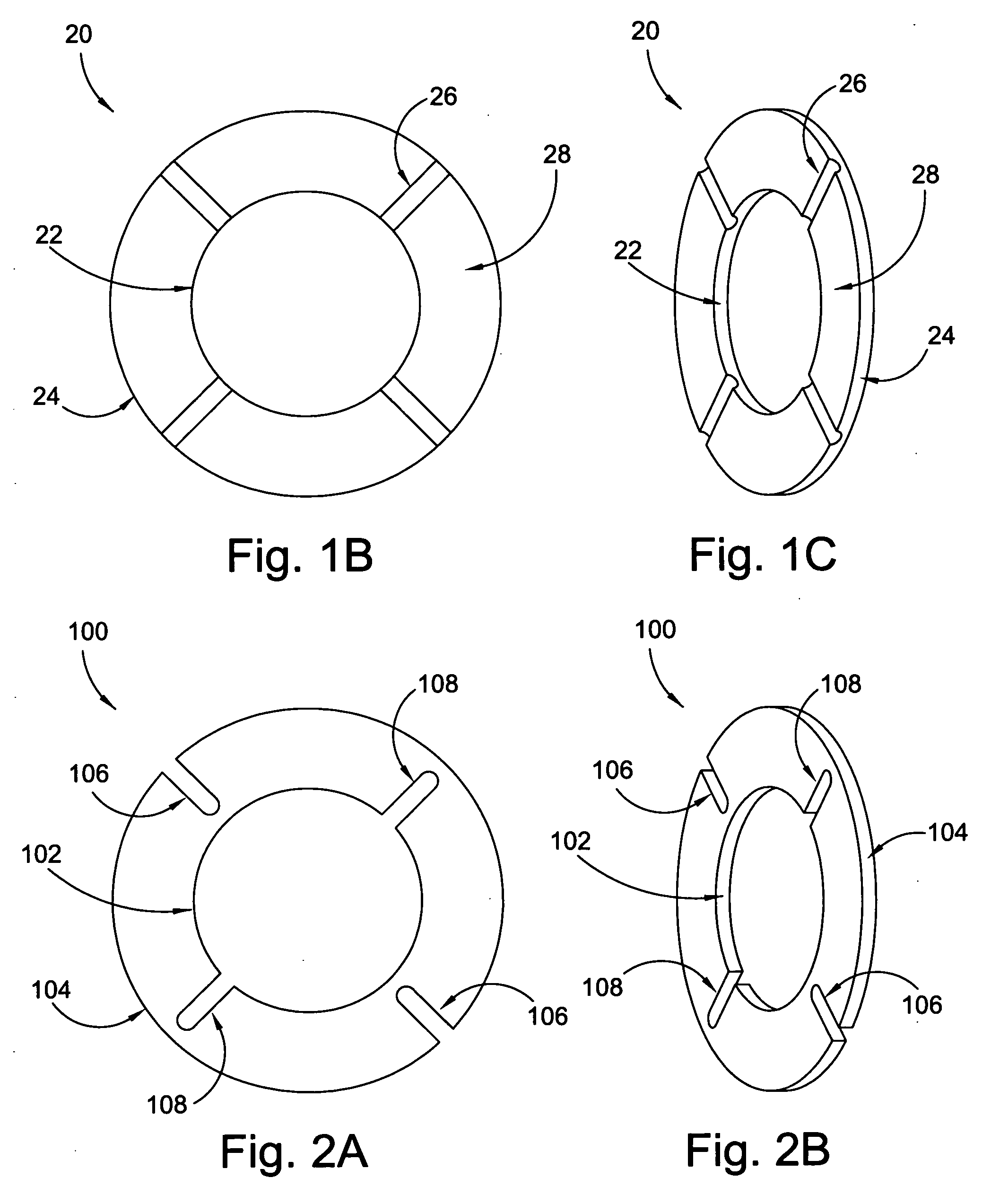
CROSS REFERENCE TO RELATED APPLICATIONS[0001]This patent application claims the benefit under 35 U.S.C. §119(e) of U.S. Provisional Application No. 61 / 069,893, filed Mar. 18, 2008, which application is incorporated herein by reference.FIELD OF THE INVENTION[0002]This invention generally relates to thrust washers, more specifically to thrust washers for torque converters, and even more specifically to thrust washers for torque converters which can be manufactured by a stamping process.BACKGROUND OF THE INVENTION[0003]FIG. 1A is a cross-sectional view of prior art torque converter 10. It should be appreciated that only the top half of the torque converter is shown in FIG. 1A, since the bottom half is substantially a mirror image of the top half. Likewise, only an upper portion of thrust washer 20 is shown. Torque converter 10 is a typical torque converter including pump 12, turbine 14, and stator 16. Torque converter 10 includes prior art thrust washer 20 engaged between turbine hub 3...

Claims


Application Information

Patent Timeline
IPC IPC(8): F16C32/06F16D33/00
CPCF16H41/24F16H2045/0294F16H45/02F16C17/04
Inventor JAMESON, JONATHAN
Owner SCHAEFFLER TECH AG & CO KG
Why Eureka
Try Eureka