
Barcode label retention device of barcode printer

Active Publication Date: 2009-09-24
TSC AUTO TECH
View PDF6 Cites 2 Cited by
  • Summary
  • Abstract
  • Description
  • Claims
  • Application Information

AI Technical Summary

Benefits of technology

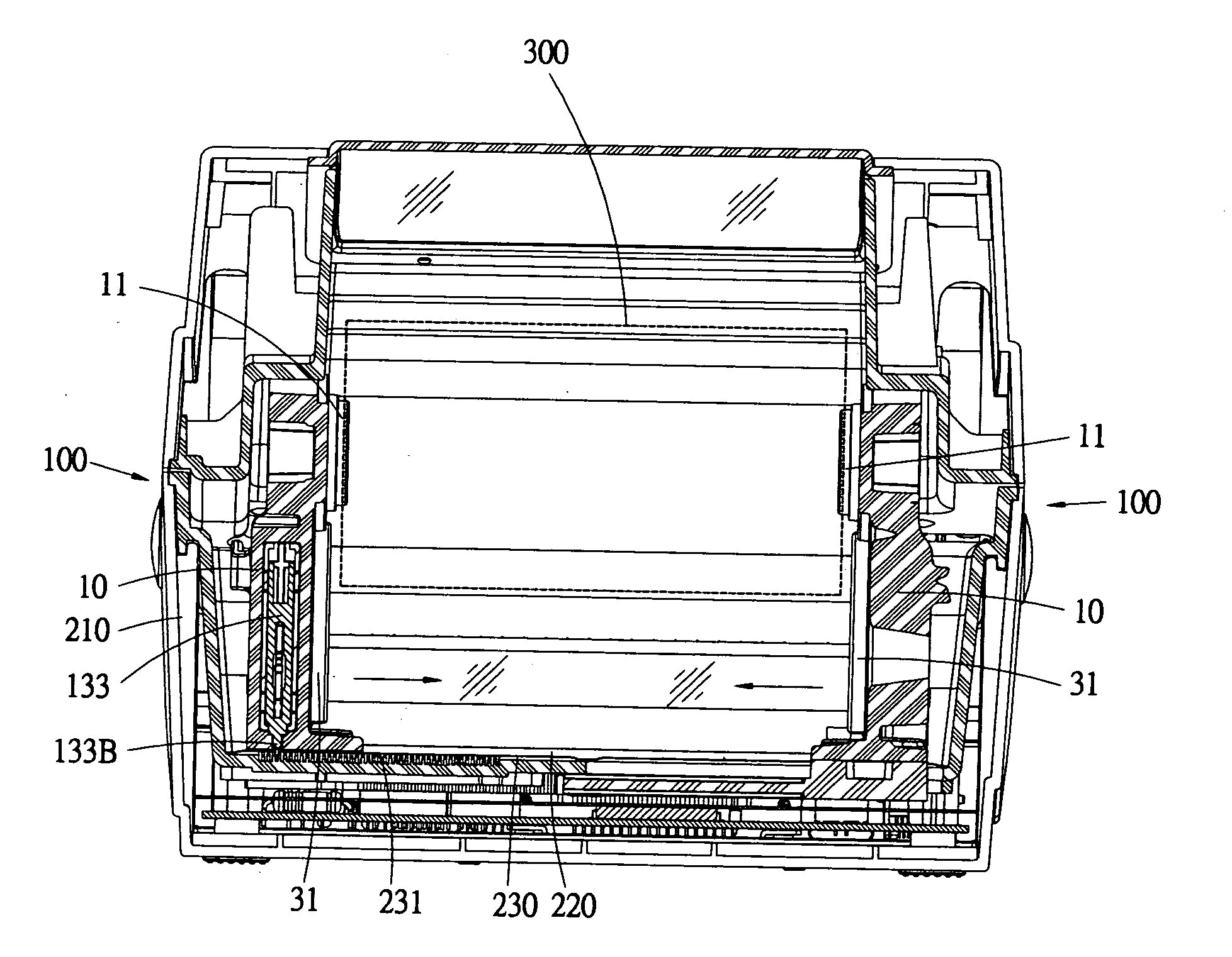
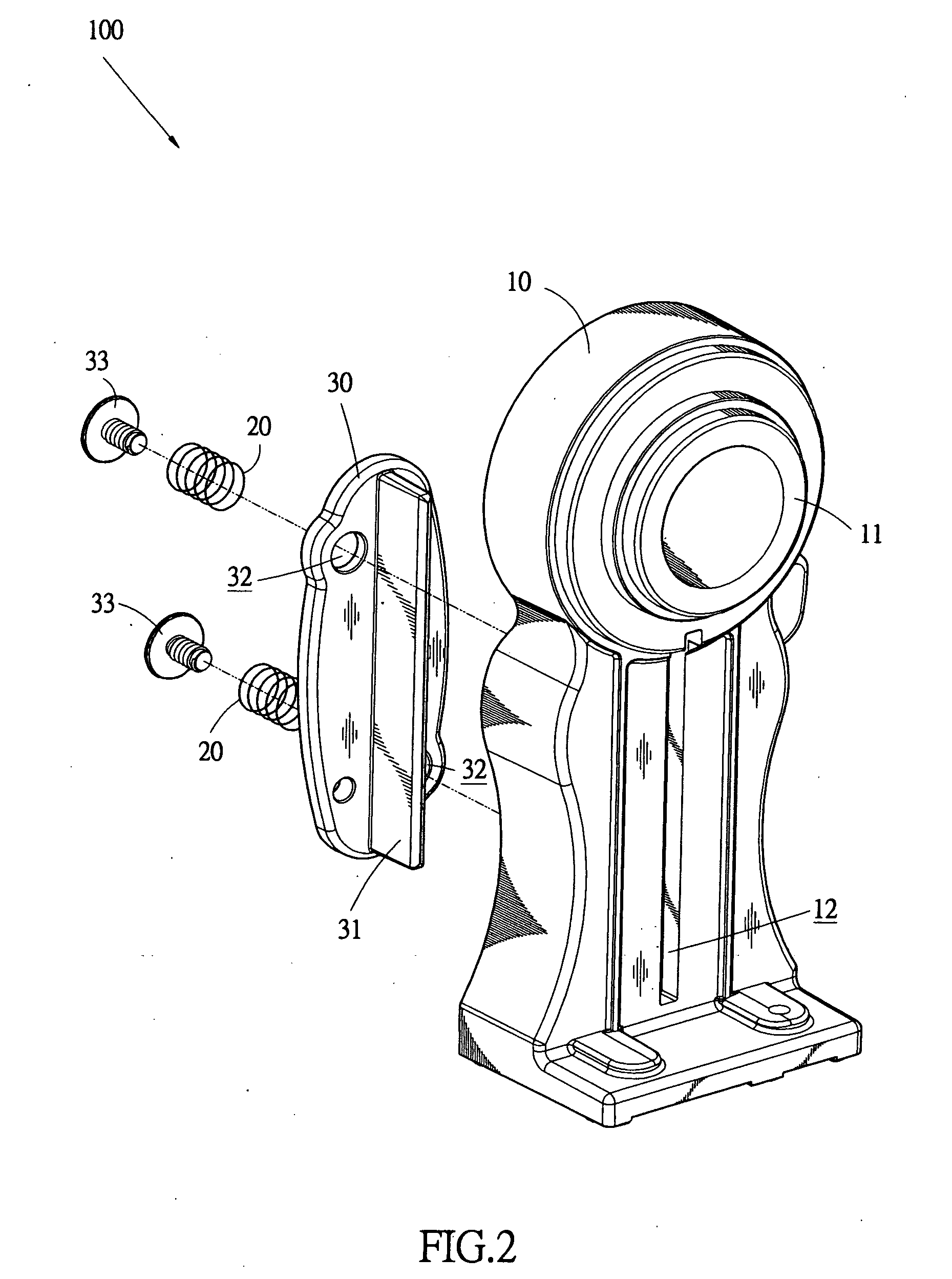
[0006]Thus, to overcome the above problems, the present invention is aimed to provide a barcode label retention device for a barcode printer, wherein the barcode label retention device comprises at least one pair of label roll retainers, at least one pair of resilient elements, and at least one pair of fixing plates. The label roll retainers are mounted inside a housing of a barcode printer and spaced from each other to receive and retain a label roll therebetween. The resilient elements are arranged inside each label roll retainer, and the fixing plates are arranged inside each label roll retainer. The fixing plate is connected to the resilient element to provide the fixing plate with resiliency for inward depressibility or outward biasing so that a front portion of the fixing plate projects inwards beyond the label roll retainer to abut against opposite ends of the label roll, whereby the label roll can be securely held by the two fixing plates engaging the opposite ends thereof and the path of a winding / unwinding operation can be stabilized.
[0007]The effectiveness of the barcode label retention device of a barcode printer in accordance with the present invention is that the barcode label roll is subjected to resilient clamping inside the barcode printer and the winding / unwinding trace of the barcode label roll can be stabilized to thereby ensure printing quality effected on the barcode label by the barcode label printer.

Problems solved by technology

Due to the fact that the barcode label retention device of the known barcode printer is not capable to properly hold a barcode label roll and to stabilize the scrolling / unwinding trace and / or operation of the barcode label roll, the printing quality realized by the known barcode printer -is substantially affected and deteriorated.

Method used


Image

  • Barcode label retention device of barcode printer
  • Barcode label retention device of barcode printer
  • Barcode label retention device of barcode printer

Examples


Embodiment Construction

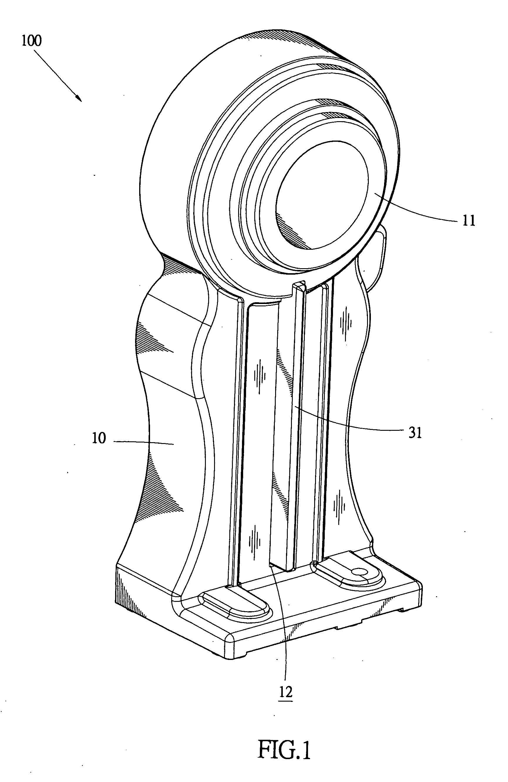
[0015]With reference to the drawings and in particular to FIGS. 1 and 2, a barcode label retention device constructed in accordance with a first embodiment of the present invention, generally designated at 100, is provided for a barcode printer, which is designated with reference numeral 200 as shown in FIGS. 5 and 6. The barcode label retention device 100 comprises at least one pair of label roll retainers 10, which are arranged inside a housing 210 of the barcode printer 200. The label roll retainers 10 each have a top portion having an inside surface opposing each other and forming at least one axle 11, whereby a label roll 300 (see FIG. 5) can be received in a space between the label roll retainers 11 with ends of the label roll 300 fit over the axles 32 respectively. Each label roll retainer 11 has a lower portion having an inside surface in which a slit 12 that extends through the label roll retainer 11 in a direction substantially parallel to the axles 32 is defined.

[0016]At ...


PUM


Abstract

A barcode label retention device is provided for a barcode printer. The barcode label retention device includes s at least one pair of label roll retainers, at least one pair of resilient elements, and at least one pair of fixing plates. The label roll retainers are mounted inside a housing of a barcode printer and spaced from each other to receive and retain a label roll therebetween. The resilient elements are arranged inside each label roll retainer, and the fixing plates are arranged inside each label roll retainer. The fixing plate is connected to the resilient element to provide the fixing plate with resiliency for inward depressibility or outward biasing so that a front portion of the fixing plate projects inwards beyond the label roll retainer to abut against opposite ends of the label roll, whereby the label roll can be securely held by the two fixing plates engaging the opposite ends thereof and the path of a winding / unwinding operation can be stabilized.

Description

BACKGROUND OF THE INVENTION[0001]1. Field of the Invention[0002]The present invention relates to a barcode label retention device of a barcode printer, and in particular to a barcode label retention device that is applicable to a barcode printer and features a pair of resiliency-based fixing plates for stabilizing a scrolling / unwinding trace and / or operation of a label roll.[0003]2. The Related Arts[0004]A conventional barcode printer includes a label roll to be printed retained inside the barcode printer for feeding a printable label to a printing mechanism for carrying out printing operations. The barcode label retention device of the known barcode printer is incapable to stabilize the trace and / or operation of scrolling / unwinding of the label and thus the label roll, during an unwinding or scrolling process, may be subjected to away or shake, leading to shifting of position at the time when the barcode label enters the printing mechanism for carrying out printing and also causing...

Claims


Application Information

Patent Timeline
IPC IPC(8): B65H75/00
CPCB41J3/01B41J15/042B65H2801/12B65H2402/543B65H23/08B65H2402/54
Inventor KUO, SHANG-SHIHLIU, CHIN-CHUAN
Owner TSC AUTO TECH
Learn More