
A printing method for inkjet printers

Pending Publication Date: 2022-03-10
CHANG YUAN +1
View PDF2 Cites 0 Cited by
  • Summary
  • Abstract
  • Description
  • Claims
  • Application Information

AI Technical Summary

Benefits of technology

The patent text describes a method to modify the placement of ink drops to prevent errors from accumulating and distributing the ink evenly. This ensures that the rounding errors do not affect the final printing result.

Problems solved by technology

This method takes lots of time and effort, and can't guarantee the printing effects.
Thirdly, paste the transfer media to the surface of the object.
Because candles are not pressed during rotation, slippage may occur to candles during rotation.
Its printing speed and printing efficiency are low.
In addition, no measures are taken to ensure uniform printing resolution if candles with different diameters are used to print on.
Though the printing speed is high, the structure of the apparatus is complicated and the printing cost is high.
For this apparatus, both the printing speed and the printing efficiency are low.
When printing on cylindrical objects with different diameters, the color of the output images may be uneven if the printing data has not been well processed.
Due to the accumulation of errors in each circle of the object's rotation, the output image may get deformed or the beginning and the end of the output image can't be well spliced.
If the actual moving speed of the carriage is greatly different from the ideal speed, the quality of the output images are bad or even the target images can't be printed out.

Method used


Image

  • A printing method for inkjet printers
  • A printing method for inkjet printers
  • A printing method for inkjet printers

Examples


Embodiment Construction

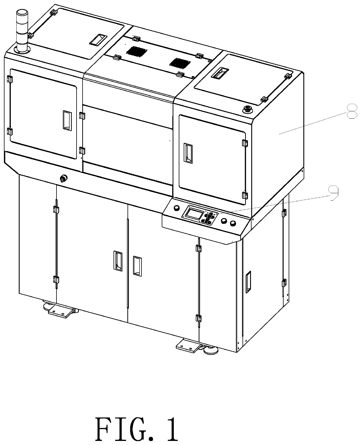
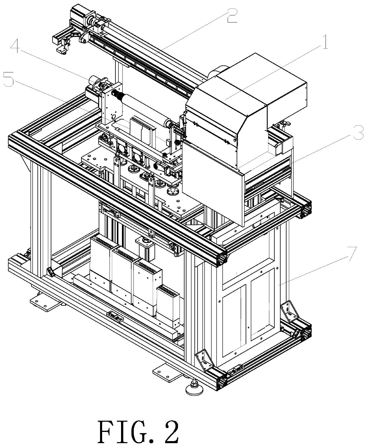
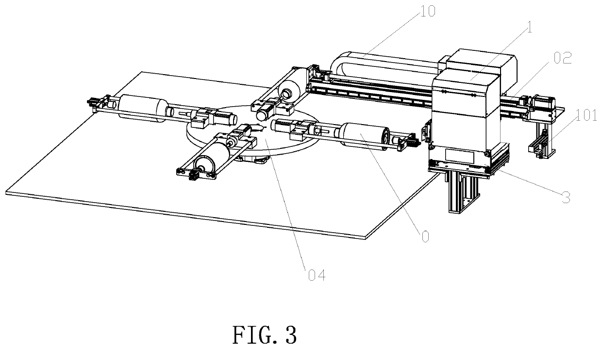
[0032]Following are detailed descriptions of the invention with the said Figs. and embodiments. As shown by FIG. 1 and FIG. 2, the inkjet printing apparatus in the first embodiment includes carriage 1, linear beam 2, head maintenance unit 3, rotating jig fixture unit 4 for the object to be printed , curing unit 5, printer base frame 7 and external covers 8. Carriage 1 is installed on the linear beam 2 and traverses along linear beam 2 in the Y axis (the first axis direction). Print heads are installed in carriage's head plate with the print heads' columns of nozzles orientated linearly parallel and above the center rotation axis of the rotating jig fixture. While carriage 1 continuously moves along the Y axis direction (the first axis direction), print heads jet ink to print on the object's cylindrical or conical surface. Ink tanks and negative pressure control system are also installed to carriage 1. Head maintenance unit 3 is installed under the linear beam 2 and the initial posit...


PUM


Abstract

The present invention provides a printing method for inkjet printers, wherein with the control system, the object to be printed continuously rotates, carriage traverses in the Y axis direction and print heads in carriage jet ink on the target printing position. Specifically, firstly get the diameter (or radius) of the object to be printed. Secondly, based on the diameter (or radius) acquired, FPGA processor calculates a frequency division factor N and a multiplication factor M independently or with the assistance of an external processor. Thirdly, with the said factor N and factor M, FPGA processor converts the encoder resolution (which is an inherent value of the encoder resolution) to calculate the actual image printing resolution. Fourthly, signals which contain the converted resolution are sent to the printing control system to print images. The printing method of the present invention can ensure excellent printing quality and uniform resolution for objects with different diameter (or radius).

Description

CROSS-REFERENCES TO RELATED APPLICATIONS[0001]This application is a national stage application of International Application No. PCT / CN2019 / 122325, filed Dec. 2, 2019, entitled “A printing method for inkjet printers”.FIELD OF THE INVENTION[0002]The present invention provides a printing method for inkjet printers, which specifically applies to printing on objects in the shape of cylinder or cone and print zones that are of cylindrical or conic shape.BACKGROUND OF THE INVENTION[0003]For existing techniques, the simplest method for printing on curved surfaces is to print on planar media and then combine the planar media with the curved surfaces. This method takes lots of time and effort, and can't guarantee the printing effects. For example, Chinese patent No. CN94115805.5 introduces a thermal transfer method for printing on curved surfaces. It takes silk paper as the transfer media and prints images on the media with high-temperature sublimation dye method. First, pre-treat the objects...

Claims


Application Information

Patent Timeline
IPC IPC(8): B41J2/045B41J3/407
CPCB41J2/04573B41J3/4073B41J2/04586B41J2/07B41J3/00B41J3/40733B41J2/2114
Inventor CHANG, YUAN
Owner CHANG YUAN
Learn More