Cutting device, machining method, and die machined by the machining method

Inactive Publication Date: 2009-09-24
PANASONIC CORP
View PDF6 Cites 4 Cited by
  • Summary
  • Abstract
  • Description
  • Claims
  • Application Information

AI Technical Summary

Benefits of technology

[0035]This machining method can reduce machining resistance during cutting, and form the blind groove with high accuracy of form in a short time.
[0036]Further, the tool may enter the work material at an angle smaller than 90° and the tool may retract from the work material at an angle larger than 90°. Thus it is possible to form the blind groove without generating burrs with high accuracy of form in a short time.
[0037]A die of the present invention has the blind groove formed by the machining method, wherein the blind groove has asperities formed on the surface of the blind groove by vibration cutting. By forming the small asperities on the surface of the die, it is possible to provide a molded product having the special effect of the asperities.
[0038]As has been discussed, the cutting device of the present invention can perform vibrating cutting using the known three-axis tool unit, thereby simultane

Problems solved by technology

Although it is difficult to operate the heavy tables of the processing machine at high speeds, it is relatively easy to minutely displace only the tools at high speeds by the actuators which can be operated at high speeds.
In a typical cutting device for realizing Fast Tool Servo, however, cutting is performed in synchronization with the position coordinate (B coordinate) of a rotation axis (B axis) and the position coordinate of one of the X axis and the Y axis (one of the X coordinate and the Y coordinate) and thus causes large machining resistance as in ordinary lathing.
The elastic deformation on the actuators results in an error of a machined shape.
Thus a typical cutting device for realizing Fast Tool Servo cannot achieve machining with higher precision.
Thus when the rotation speed is reduced, it is not possible to perform high-precision machining.
In a typical vibration cutting device for realizing elliptical vibration cutting

Method used


Image

  • Cutting device, machining method, and die machined by the machining method
  • Cutting device, machining method, and die machined by the machining method
  • Cutting device, machining method, and die machined by the machining method

Examples


Example

[0064]Referring to FIGS. 1 to 17, the following will describe a cutting device, a machining method, and a die machined by the machining method according to embodiments of the present invention.

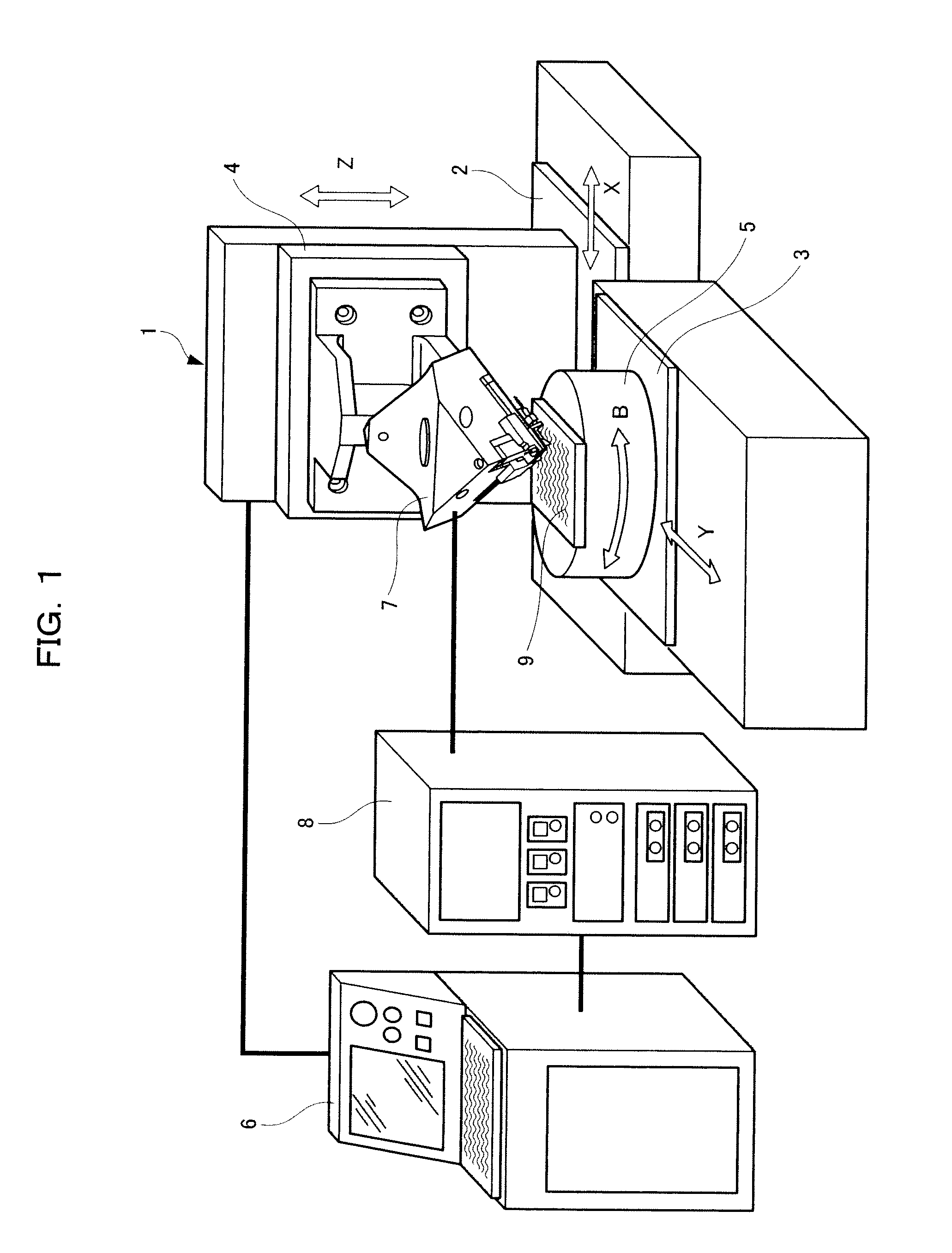
[0065]FIG. 1 shows the overall-configuration of the cutting device according to the embodiment of the present invention. First, referring to FIG. 1, the following will describe the overall configuration of the cutting device according to the embodiment.

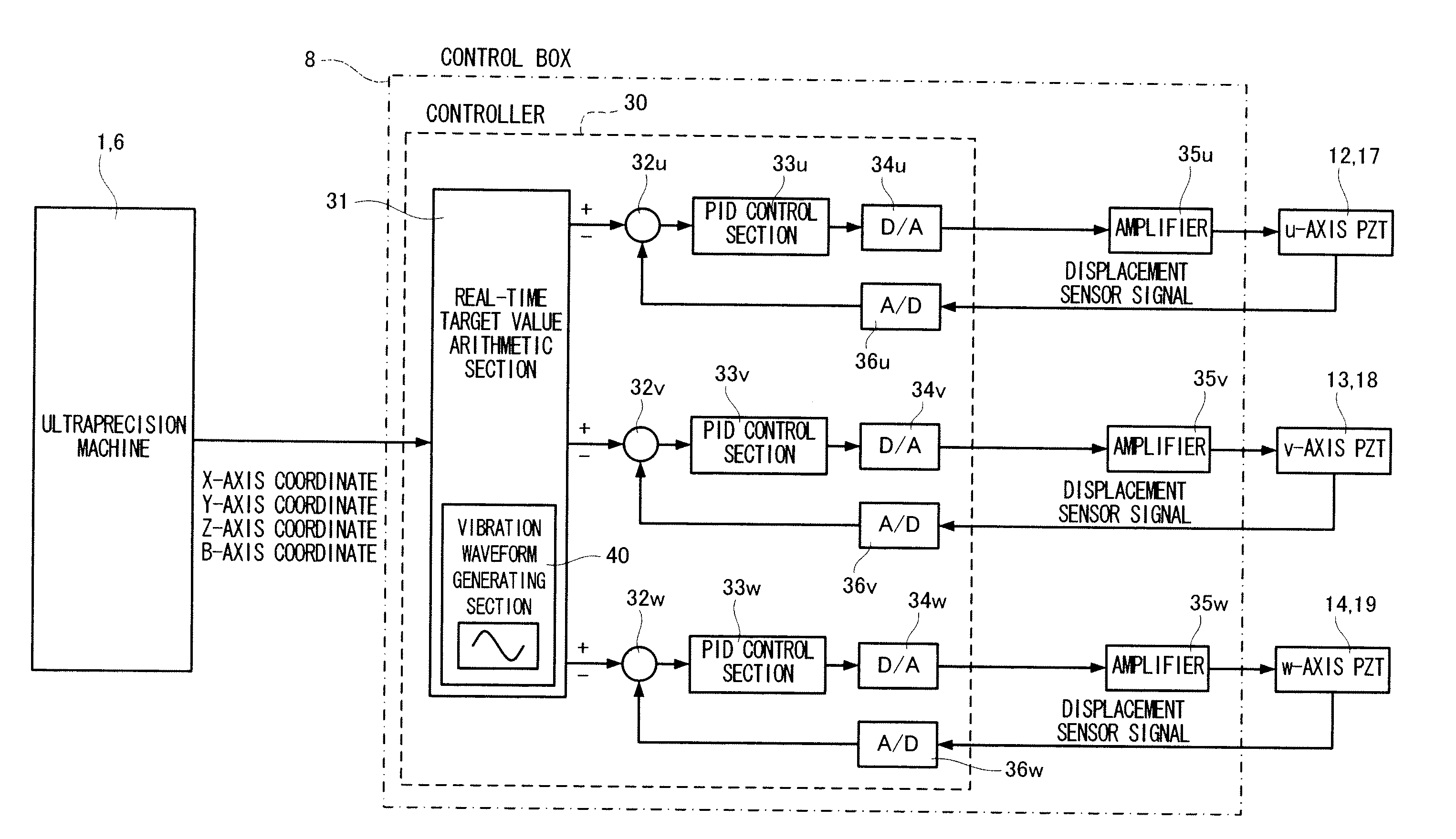
[0066]As shown in FIG. 1, the cutting device is made up of an ultraprecision machine 1, a NC controller 6 for controlling the operations of the movable axes of the ultraprecision machine 1 according to a NC program, a three-axis tool unit 7 mounted on the ultraprecision machine 1, and a control box 8 for a three-axis tool unit.

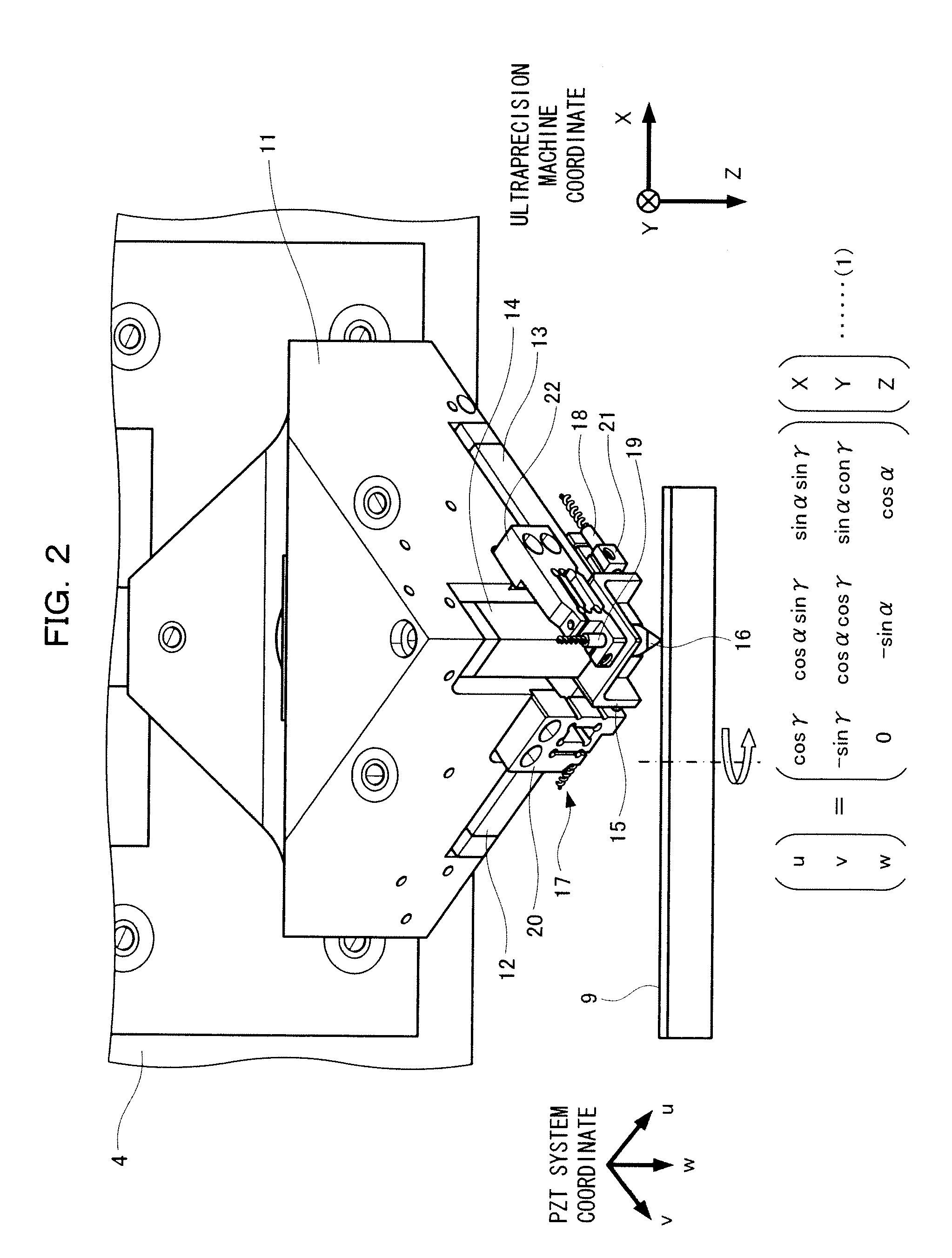
[0067]The ultraprecision machine 1 is made up of an X-axis table 2, a Y-axis table 3, and a Z-axis table 4 which are respectively operated in the X-axis, Y-axis, and Z-axis directions orthogonal to one another, and a B-axi...


PUM


Abstract

A cutting device is provided which can simultaneously achieve a shorter machining time, lower machining resistance during cutting, and high-precision machining. To be specific, the cutting device of the present invention includes a three-axis tool unit including a first actuator operating in a u direction, a second actuator operating in a v direction orthogonal to the u direction, a third actuator operating in a w direction orthogonal to the u direction and the v direction, a tool holder disposed at the intersection of the u direction, the v direction, and the w direction, a tool mounted in the tool holder, and three sensors for measuring the displacements of the first, second, and third actuators, respectively and feeding back displacement signals representing the measured displacements, wherein the first, second, and third actuators of the three-axis tool unit vibrate so as to perform vibration cutting on a work material.

Description

FIELD OF THE INVENTION[0001]The present invention relates to a cutting device which can minutely operate a tool independently in three axial directions, a machining method, and a die machined by the machining method.BACKGROUND OF THE INVENTION[0002]In the prior art, a technique called Fast Tool Servo has been known. In Fast Tool Servo, actuators for supporting tools are driven at high speeds at frequencies many times higher than the response frequencies of the tables (movable axes) of a processing machine. The actuators are driven on the order of several hundreds hertz and include a piezoelectric element, a magnetostrictor, and a voice coil which can be operated at high speeds. Although it is difficult to operate the heavy tables of the processing machine at high speeds, it is relatively easy to minutely displace only the tools at high speeds by the actuators which can be operated at high speeds.[0003]Fast Tool Servo is described in, for example, “Japanese Patent Laid-Open No. 2007-...

Claims


Application Information

Patent Timeline
IPC IPC(8): G05B19/402
CPCB23B29/125B23Q2230/004B23Q1/34B23B2260/108Y10T70/5549
Inventor TAKAHASHI, MASAYUKITASHIRO, ISAO
Owner PANASONIC CORP
Why Eureka
Try Eureka