Method and apparatus for polishing a workpiece surface

Inactive Publication Date: 2006-10-17
NEDERLANDSE ORG VOOR TOEGEPAST-NATUURWETENSCHAPPELIJK ONDERZOEK (TNO)
View PDF6 Cites 6 Cited by
  • Summary
  • Abstract
  • Description
  • Claims
  • Application Information

AI Technical Summary

Benefits of technology

[0005]To that end, the invention provides a method for machining a workpiece surface, with which, under the influence of a polishing operation, an area to be machined of the workpiece surface is machined and, during machining, the displacement of the area to be machined relative to a reference area rigidly coupled to the workpiece surface is monitored by following over time a phase difference between a measuring beam and a reference beam and by converting it into a displacement relative to a reference area, while, by choosing the change of the phase difference between measurements to be in the interval (−π, π), the total displacement can be obtained by addition. By monitoring during machining, through interferometry, the displacement of the area to be machined relative to a reference area rigidly coupled to the workpiece surface, the form change of the workpiece can be monitored during machining and, without frequent clamping and unclamping of the workpiece for a separate measuring operation, a very great form accuracy of the surface can be achieved. The rigid coupling between the area to be machined and the reference area then enables reliable measurements with interferometry, while monitoring only the relative movement of an area to be machined relative to a reference area simplifies the use of interferometry.

Problems solved by technology

A problem which occurs with the known operations is that it is relatively time-consuming to manufacture a workpiece whose surface has a very great form accuracy.
This is chiefly caused by the fact that it is often not possible to measure the form of the workpiece during machining.

Method used


Image

  • Method and apparatus for polishing a workpiece surface
  • Method and apparatus for polishing a workpiece surface
  • Method and apparatus for polishing a workpiece surface

Examples


Embodiment Construction

[0051]Although, in the following example, the polishing operation is carried out with the aid of a fluid jet polishing device, it will be clear to the skilled person that the invention can be carried out analogously in combination with a different material removing or non-material removing polishing operation.

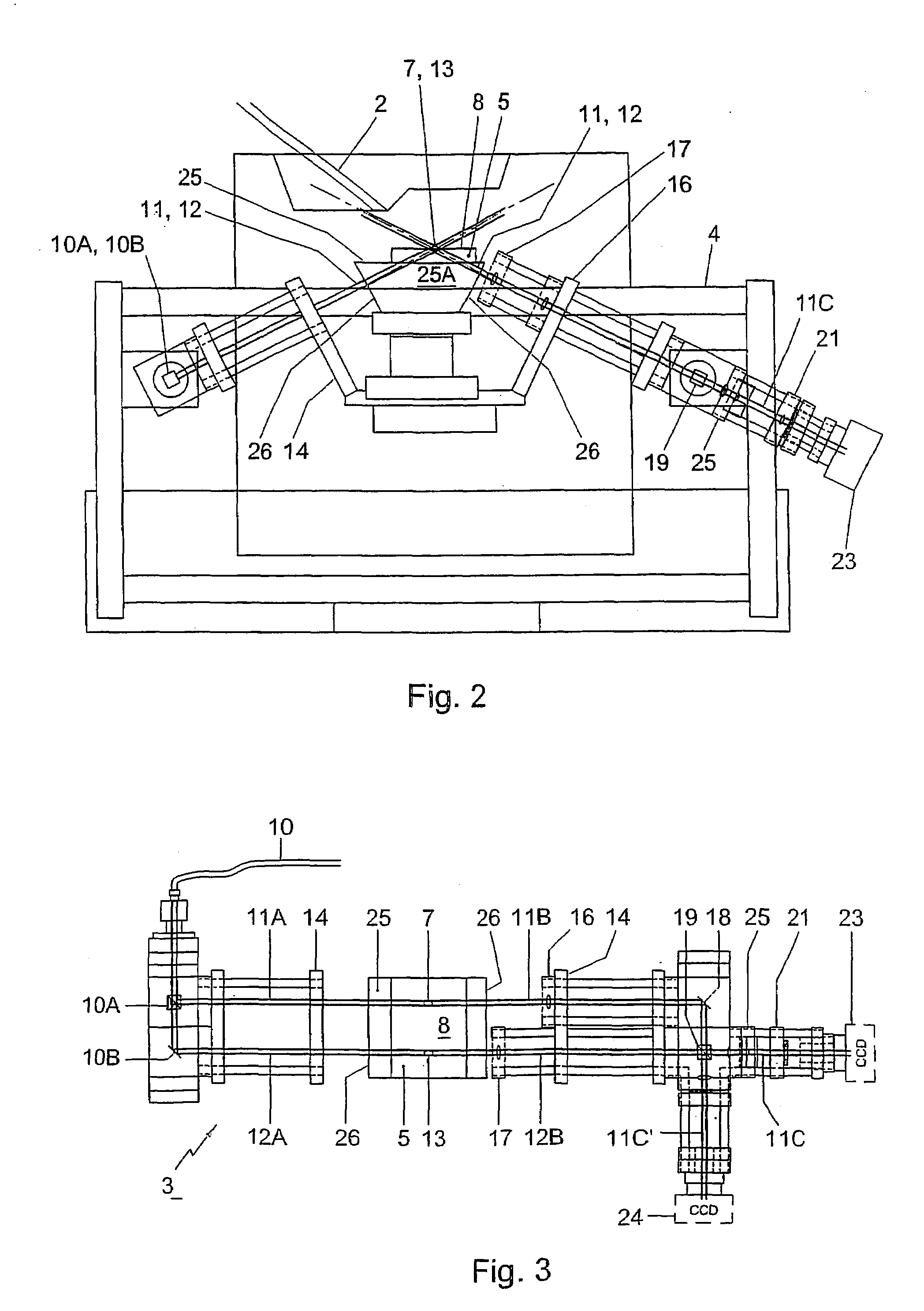
[0052]The technique of fluid jet polishing is generally known and described, inter alia, in Dutch patent application 1007589 in the name of Nederlandse Organisatie voor Toegepast Natuurwetenschappelijk Onderzoek-TNO of Delft. The interferometrical technique described in this exemplary embodiment is known to the skilled person as TPU (Temporal Phase Unwrapping).

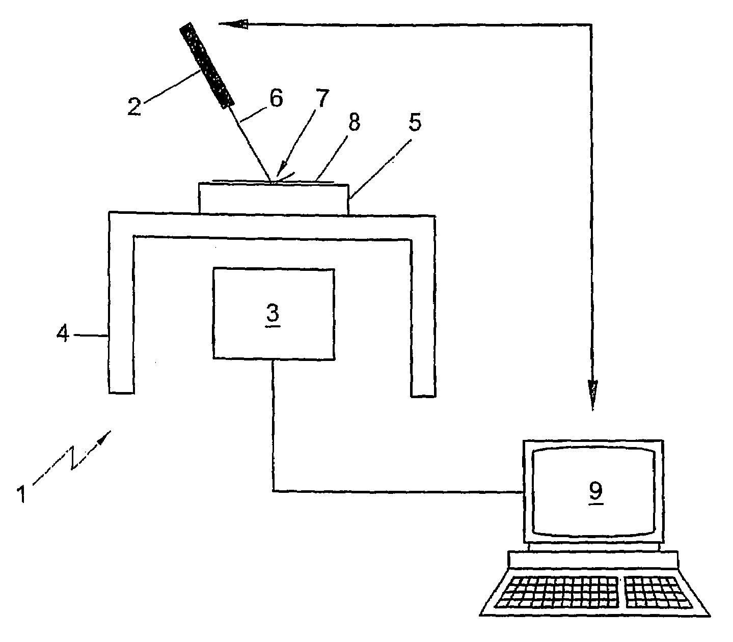
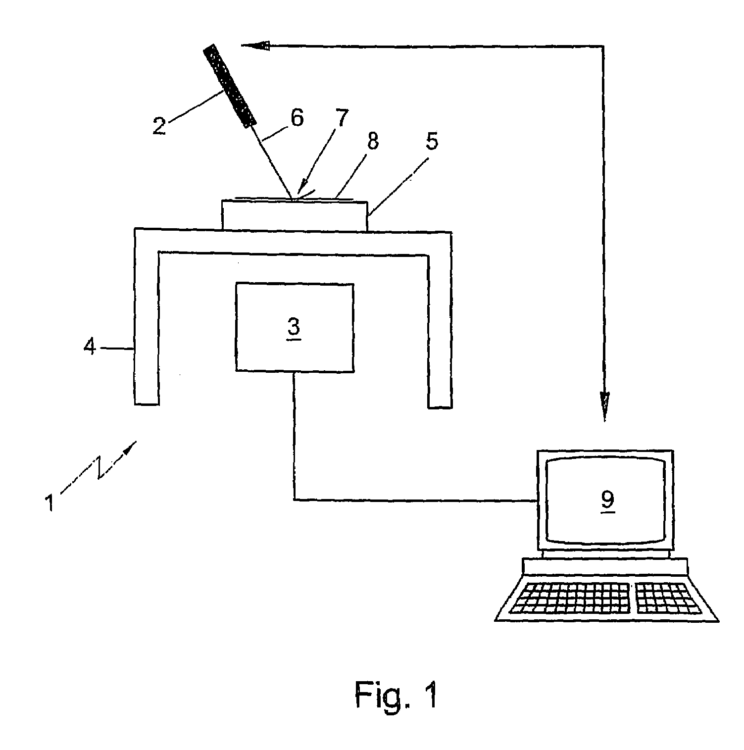
[0053]With reference to FIGS. 1–3, a machining apparatus 1 is shown having a polishing tool designed as a fluid jet polishing device 2, and a measuring tool, designed as a laser interferometer 3. The machining apparatus 1 further comprises a workpiece table 4 on which a workpiece 5 of BK7 is clamped which can be machined ...


PUM

PropertyMeasurementUnit
Areaaaaaaaaaaa
Transparencyaaaaaaaaaa
Phaseaaaaaaaaaa

Abstract

The invention relates to a method for machining a workpiece surface, wherein an area to be machined of the workpiece surface is machined under the influence of a polishing operation and wherein, during the machining, the displacement of the area to be machined relative to a reference area rigidly coupled to the workpiece surface is monitored by means of interferometry. The invention further relates to a machining apparatus, comprising a polishing tool and a measuring tool, while the measuring tool comprises an interferometer. Preferably, the polishing tool comprises a fluid jet polishing device.

Description

BACKGROUND OF THE INVENTION[0001]The invention relates to a method for machining a workpiece surface, in which an area to be machined of the workpiece surface is machined under the influence of a polishing operation.[0002]Such a method is generally known and is often used for polishing surfaces of optical components, such as refractive optical components, for instance lenses or windowpanes from glass, quartz or BK7, and reflective optical components such as mirrors, from metal or ceramics. Known methods for polishing, in addition to polishing with a grinding template and grinding paste, are, generally, material-removing techniques such as SPDT (single point diamond turning), CCP (computer controlled polishing), MRF (magneto-rheologic finishing), FJP (fluid jet polishing) and EEM (Elastic Emission Machining), IBF (Ion Beam Figuring) and IBP (Ion Beam Polishing).[0003]A problem which occurs with the known operations is that it is relatively time-consuming to manufacture a workpiece wh...

Claims


Application Information

Patent Timeline
IPC IPC(8): B24B49/00B24B1/00B23Q17/24B24C1/00B24B13/06B24B49/04B24B49/12B24C1/08
CPCB24B13/06B24B49/04B24B49/12B24C1/08
Inventor VAN BRUG, HEDSER
Owner NEDERLANDSE ORG VOOR TOEGEPAST-NATUURWETENSCHAPPELIJK ONDERZOEK (TNO)
Why Eureka
Try Eureka