Bathroom fixture attachment device including a rotary coupling

a technology of attachment device and bathroom fixture, which is applied in the direction of washstand accessories, lightening support devices, washstands, etc., can solve the problems of inability to bear the load required, difficult adjustment, and typical prior art mounting devices, and achieve the effect of concealing all mounting hardware and mounting quickly and easily

Inactive Publication Date: 2009-10-01
HARDWARE RESOURCES
View PDF49 Cites 35 Cited by
  • Summary
  • Abstract
  • Description
  • Claims
  • Application Information

AI Technical Summary

Benefits of technology

[0007]The preferred embodiment of the present invention provides a rotary coupling mechanism that securely attaches common household fixtures to a wall. The invention allows the fixtures to be mounted quickly and easily to the wall and further conceals all mounting hardware. The invention...

Problems solved by technology

The typical prior art mounting devices are unacceptable because many times, the set screws are small, making them difficult to adjust.
Also, the set screws are generally incapable of bearing the load required because of their small size and therefore, ...

Method used


Image

  • Bathroom fixture attachment device including a rotary coupling
  • Bathroom fixture attachment device including a rotary coupling
  • Bathroom fixture attachment device including a rotary coupling

Examples


Embodiment Construction

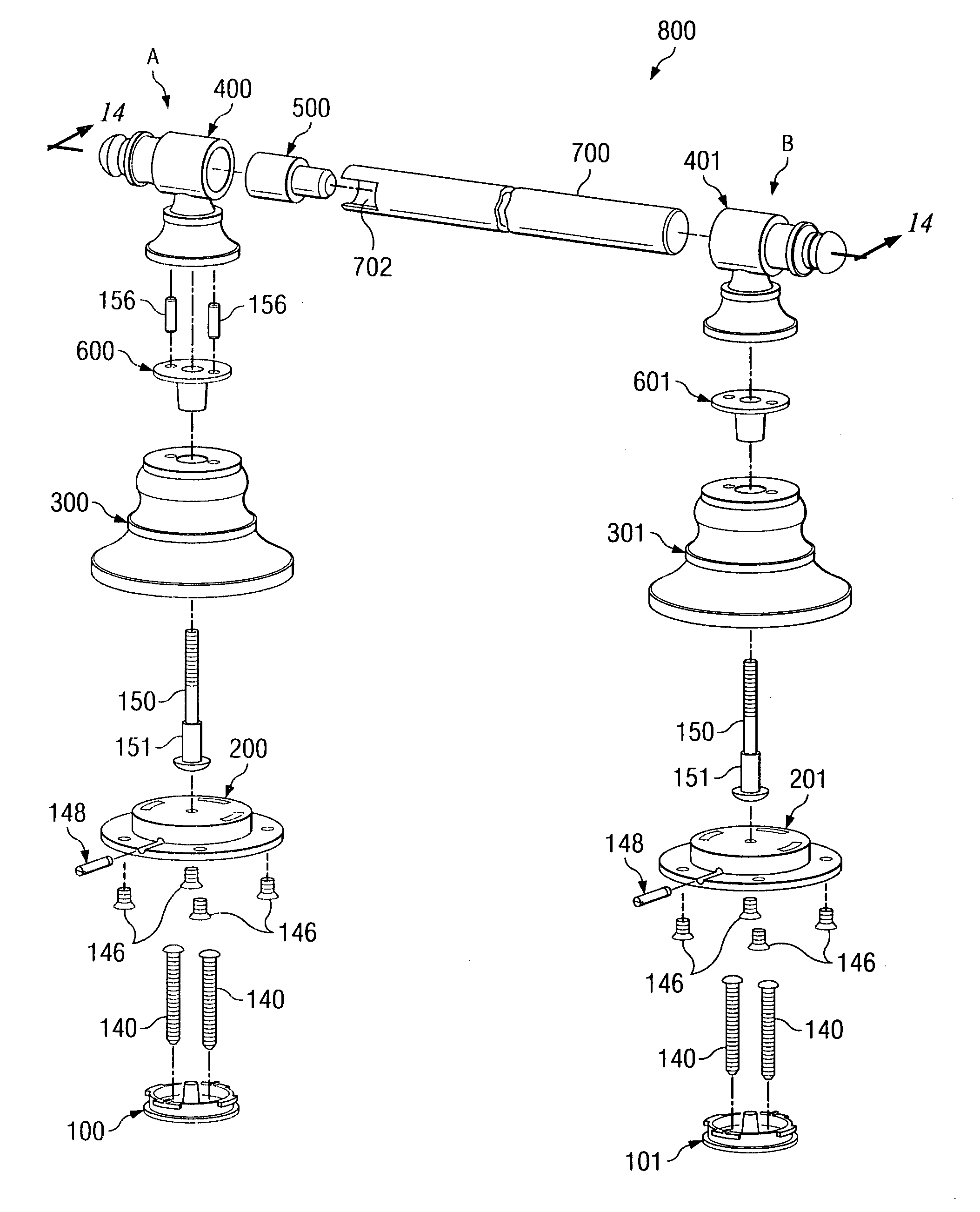
[0037]In the descriptions that follow, like parts are marked throughout the specification and drawings with the same numerals, respectively. The drawing figures are not necessarily drawn to scale and certain figures may be shown in exaggerated or generalized form in the interest of clarity and conciseness.

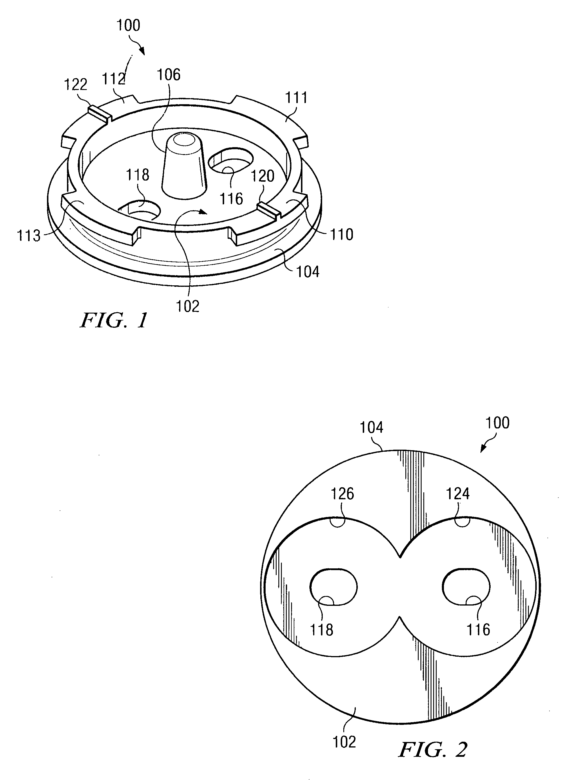
[0038]FIGS. 1 and 2 show wall bracket 100. Wall bracket 100 is generally cylindrical in shape. Wall bracket 100 is enclosed on one end by base 102. Base 102 extends past the cylindrical wall of wall bracket 100 to form lip 104. Flanges 110, 111, 112, and 113 extend outwardly from the open end of wall bracket 100. In the preferred embodiment, flanges 110, 111, 112, and 113 are spaced at 90° intervals around wall bracket 100 and each occupies between about 40° and 45° of the perimeter of wall bracket 100. Wall bracket 100 further includes a centrally located boss 106 which extends from the center of base 102. Two diametrically opposed oblong openings, mounting holes 116 and 118, flan...


PUM


Abstract

The invention disclosed provides a rotary coupling mechanism that securely attaches common household fixtures to a wall. The invention is comprised of a wall bracket, a base bracket, a cam pin, and two mounting screws. Flanges on the base bracket rotationally engage flanges on the wall bracket and the cam pin inserted through the base bracket rotates to hold the flanges and secure the base bracket to the wall bracket. An alternate embodiment of the invention is comprised of a wall bracket and a base bracket having flanges with canted surfaces. A locking pin holds the brackets together after the flanges are rotationally engaged. For each application of the coupling mechanism, a decorative body conceals the apparatus. The decorative body is rigidly connected or pivotally connected to a decorative cap. The decorative cap retains various household fixtures such as paper holders, towel racks, or shelves.

Description

FIELD OF THE INVENTION[0001]The present invention relates to a coupling mechanism. In particular, the invention relates to a rotary coupling mechanism secured to a wall and used to support various decorative and functional fixtures in a household.BACKGROUND OF THE INVENTION[0002]In the prior art, kitchen and bathroom fixtures such as paper holders, shelves and towel rods are secured to vertical walls with mounting devices made of various compositions. Generally, the walls are drywall or sheetrock and in some cases include a tile or stone facade. The prior art mounting devices are generally comprised of two pieces. The first piece usually includes a flat plate having angled flanges affixed to the wall with screws or bolts. The second piece is usually a decorative cover affixed to the plate through the use of set screws. The set screws thread through the lower plate and engage the angled flanges. The typical prior art mounting devices are unacceptable because many times, the set screw...

Claims


Application Information

Patent Timeline
IPC IPC(8): F16B2/18A47K10/22
CPCA47K10/10A47K2201/02A47K10/38
Inventor LOWE, MARK JEFFREYMILLER, KENNY LAVELLE
Owner HARDWARE RESOURCES
Why Eureka
Try Eureka