Laminator

a technology of diaphragm and laminator, which is applied in the field of laminators, can solve the problems of increasing the downtime of the laminator, generating costs for the replacement of the diaphragm, and inability to maintain a vacuum, and achieves the effect of easy removal

Inactive Publication Date: 2010-06-01
NISSHINBO IND INC
View PDF19 Cites 0 Cited by
  • Summary
  • Abstract
  • Description
  • Claims
  • Application Information

AI Technical Summary

Benefits of technology

[0016]The present invention provides a laminator of which the diaphragm can be mounted and removed easily without the use of a mounting frame.
[0021]In the laminator having the construction described above, the diaphragm is fixed in place on the lateral side surfaces of the upper chamber, rendering use of a mounting frame unnecessary. The unique effect of such an arrangement is that the diaphragm can be mounted quickly and easily.

Problems solved by technology

However, with such a mounting arrangement, when the diaphragm expands tensile stress is exerted on the portions of the periphery of the diaphragm that are compressed by the mounting frame.
This tensile stress extends to the diaphragm bolt hole portions as well, the bolt holes tear, gradually grow large, and are damaged, and eventually become unable to maintain a vacuum.
Thus, replacing the diaphragm generates costs and adds to down-time of the laminator.
As a result, mounting frames are also getting larger and therefore also heavier, which means that they can be awkward to handle.

Method used


Image

  • Laminator
  • Laminator
  • Laminator

Examples


Embodiment Construction

[0029]A detailed description will now be given of illustrative embodiments of the present invention, with reference to the accompanying drawings.

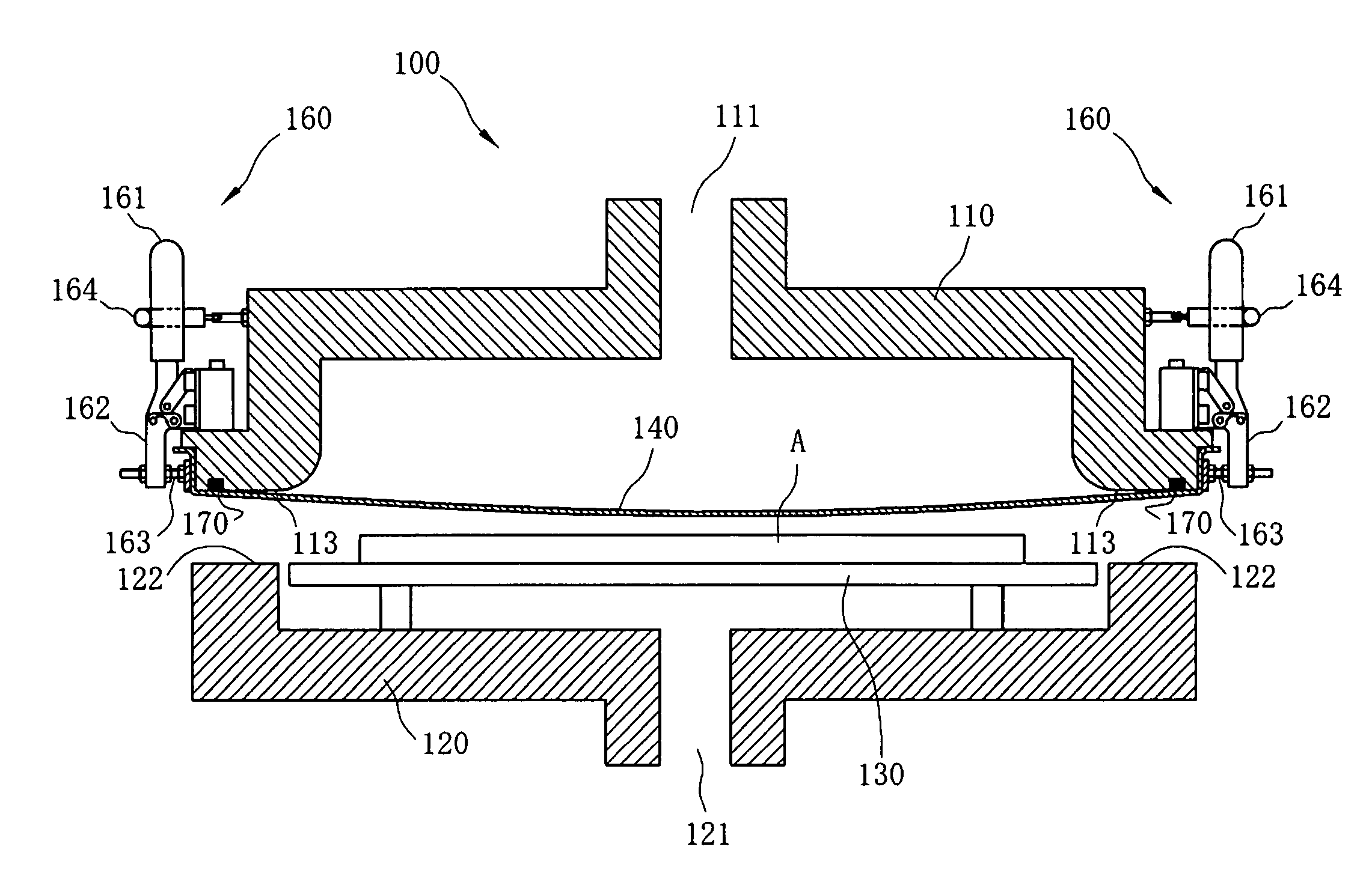
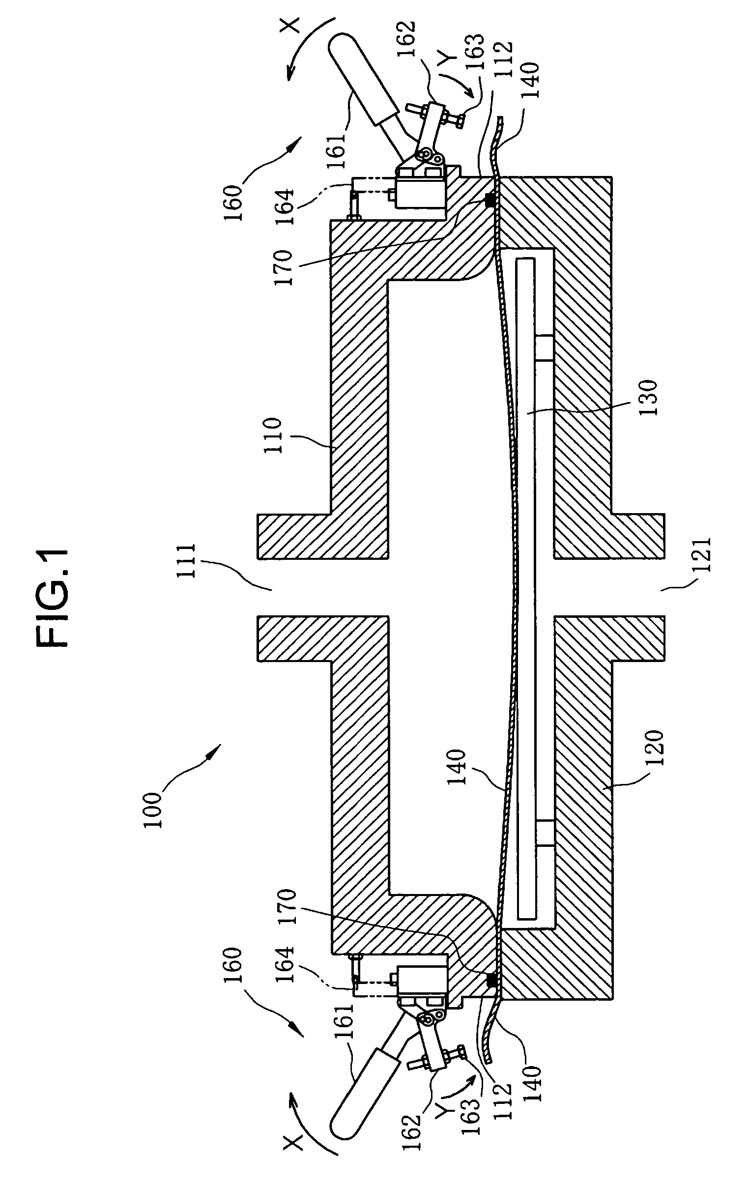
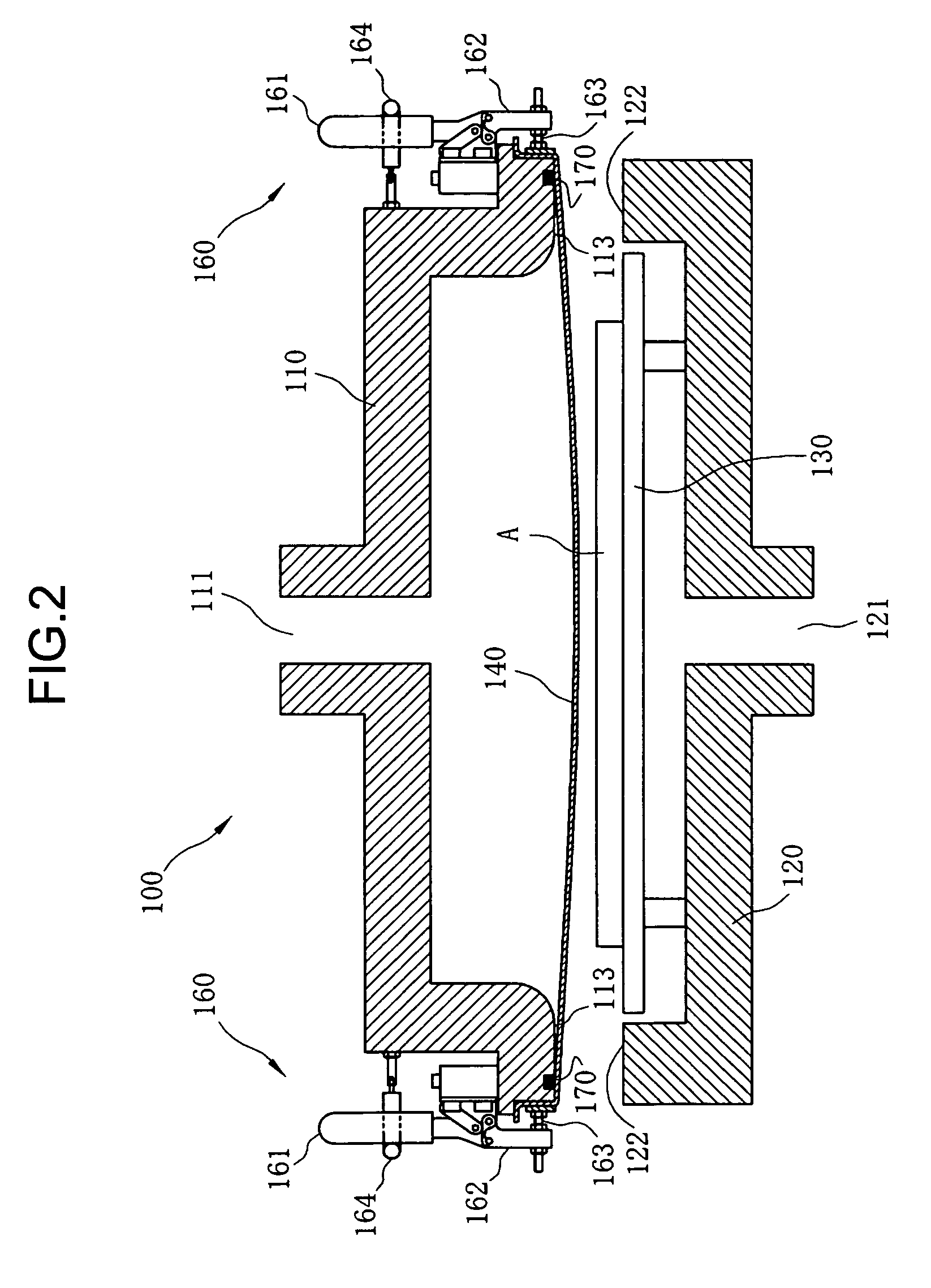
[0030]FIG. 1 is a sectional view of essential portions of a laminator according to the present invention. FIG. 2 is a sectional view of the laminator of FIG. 1, with a diaphragm clamped in place. FIG. 3 is a plan view of the upper chamber with the diaphragm mounted thereon.

[0031]The laminator 100 includes an upper chamber 110 and a lower chamber 120. A bottom face 113 of the upper chamber 110 and a top face 122 of the lower chamber 120 are rectangles of the same size. Three suction ports 111 coupled to a vacuum pump, not shown, are provided at a top of the upper chamber 110. Similarly, three other suction ports 121, not shown in the plan view, are provided at a bottom of the lower chamber 120. A support pedestal 30 is provided in an interior space of the upper chamber 120.

[0032]The diaphragm is mounted as follows: First, the upper chamber 1...


PUM

PropertyMeasurementUnit
tensile stressaaaaaaaaaa
shapeaaaaaaaaaa
sizeaaaaaaaaaa

Abstract

A laminator 100 in which the diaphragm can be mounted simply and easily without the use of a mounting frame. The laminator 100 includes an upper chamber 110, on the bottom surface of which is mounted the diaphragm 140, and a lower chamber 120 on which the upper chamber 110 is stacked and in which is disposed a support base 130 on which a workpiece A that is to be laminated is set. The diaphragm 140 is larger than the upper chamber 110, and an excess portion of the diaphragm that protrudes outside the upper chamber when the diaphragm is mounted on the upper chamber is folded upward and clamped against the sides of the upper chamber by multiple clamps to fix the diaphragm in place on the upper chamber.

Description

CLAIM FOR PRIORITY[0001]The present specification claims priority pursuant to 35 U.S.C. §119 from Japanese Patent Application No. 2007-155801, filed on Jun. 13, 2007 in the Japan Patent Office, the entire contents of which are hereby incorporated by reference herein.BACKGROUND[0002]1. Field of the Invention[0003]The present invention relates to a laminator for manufacturing laminated objects such as photovoltaic cell modules, and more particularly, to a diaphragm mounting structure used in such a laminator.[0004]2. Description of the Background Art[0005]Examples of conventional laminators used to manufacture photovoltaic cell modules are described, for example, in Japanese Unexamined Patent Application Publication No. 9-141743 (JP-H09-141743-A), Japanese Unexamined Patent Application Publication No. 11-204811 (JP-H11-204811-A), and Japanese Registered Utility Model No. 3037201 (JP-3037201-U). For these types of laminators, an arrangement is employed in which upper and lower chambers...

Claims


Application Information

Patent Timeline
Patent Type & Authority Patents(United States)
IPC IPC(8): B32B37/00
CPCB30B5/02B32B37/0046Y10T156/18B32B2457/12Y02E10/50H01L31/18H01L31/04
Inventor KASAHARA, MASATONAKAMURA, SHIN
Owner NISSHINBO IND INC
Why Eureka
Try Eureka