Planar rotation mechanism of supporting device

Active Publication Date: 2009-10-01
JARLLYTEC CO LTD
View PDF14 Cites 22 Cited by
  • Summary
  • Abstract
  • Description
  • Claims
  • Application Information

AI Technical Summary

Benefits of technology

[0009]One object of the present invention is to provide a planar rotation mechanism, wherein a retaining member and a rotating member are designed with a rail fashion, so when the rotating member is operated with a planar rotation with respect to the retaining member, the planar rotation from vertical to horizontal or vice versa can be operated without considerations of a height limit between an object to be supported and

Problems solved by technology

Because there is a height between the bottom end of the monitor main body and the base seat, if the height is smaller than the distance between one bottom corner of the bottom end of the monitor main body and the pivotal shaft section, when the planar rotation is operated, the bottom corner of the bottom end of the monitor main body will hit against a surface of a desk, and this

Method used


Image

  • Planar rotation mechanism of supporting device
  • Planar rotation mechanism of supporting device
  • Planar rotation mechanism of supporting device

Examples


Example

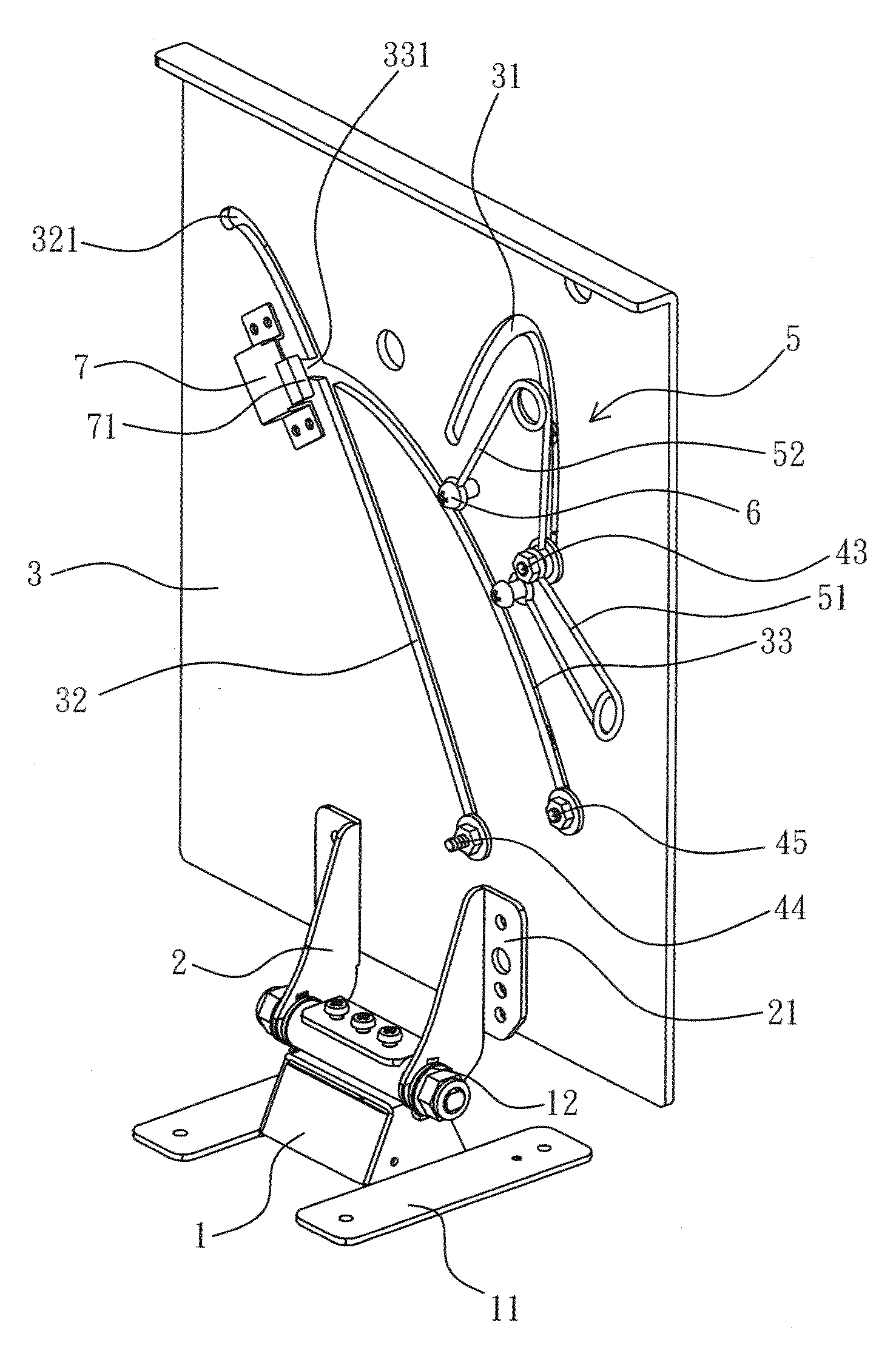
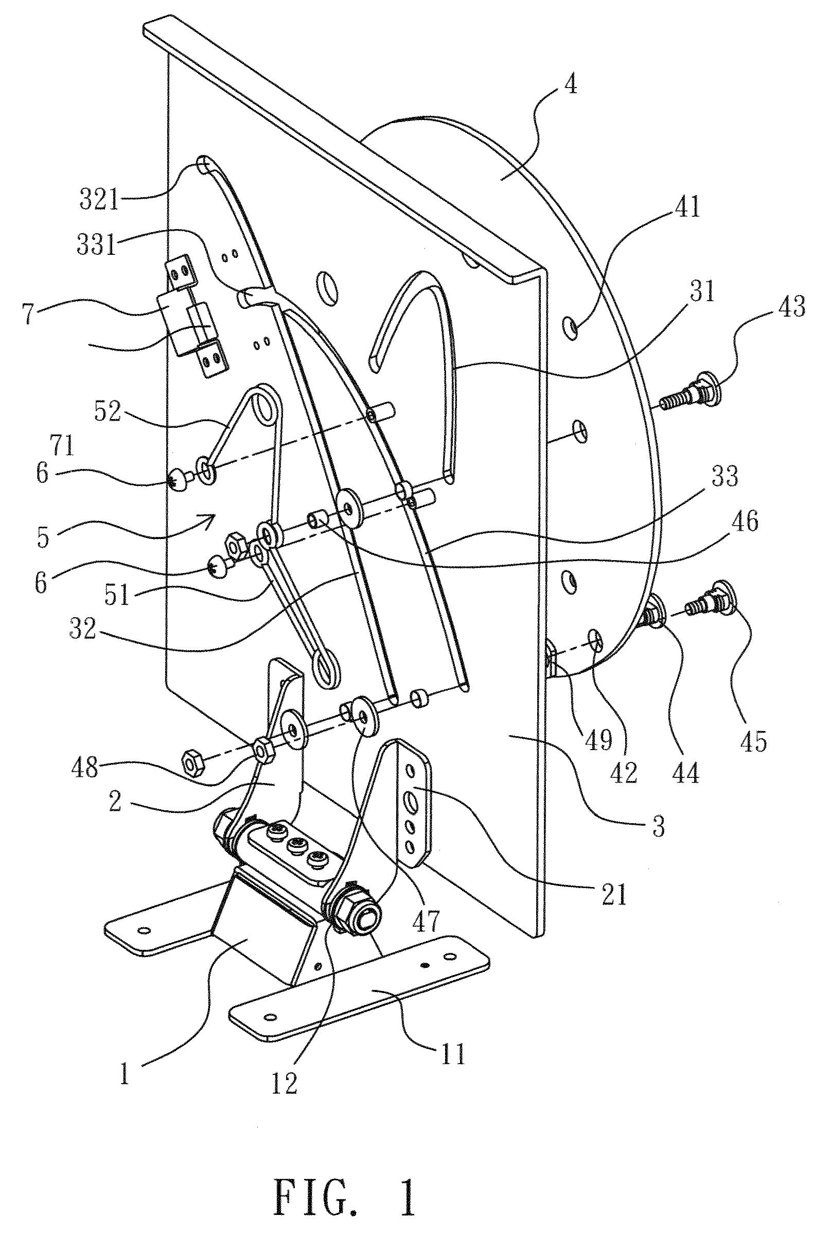
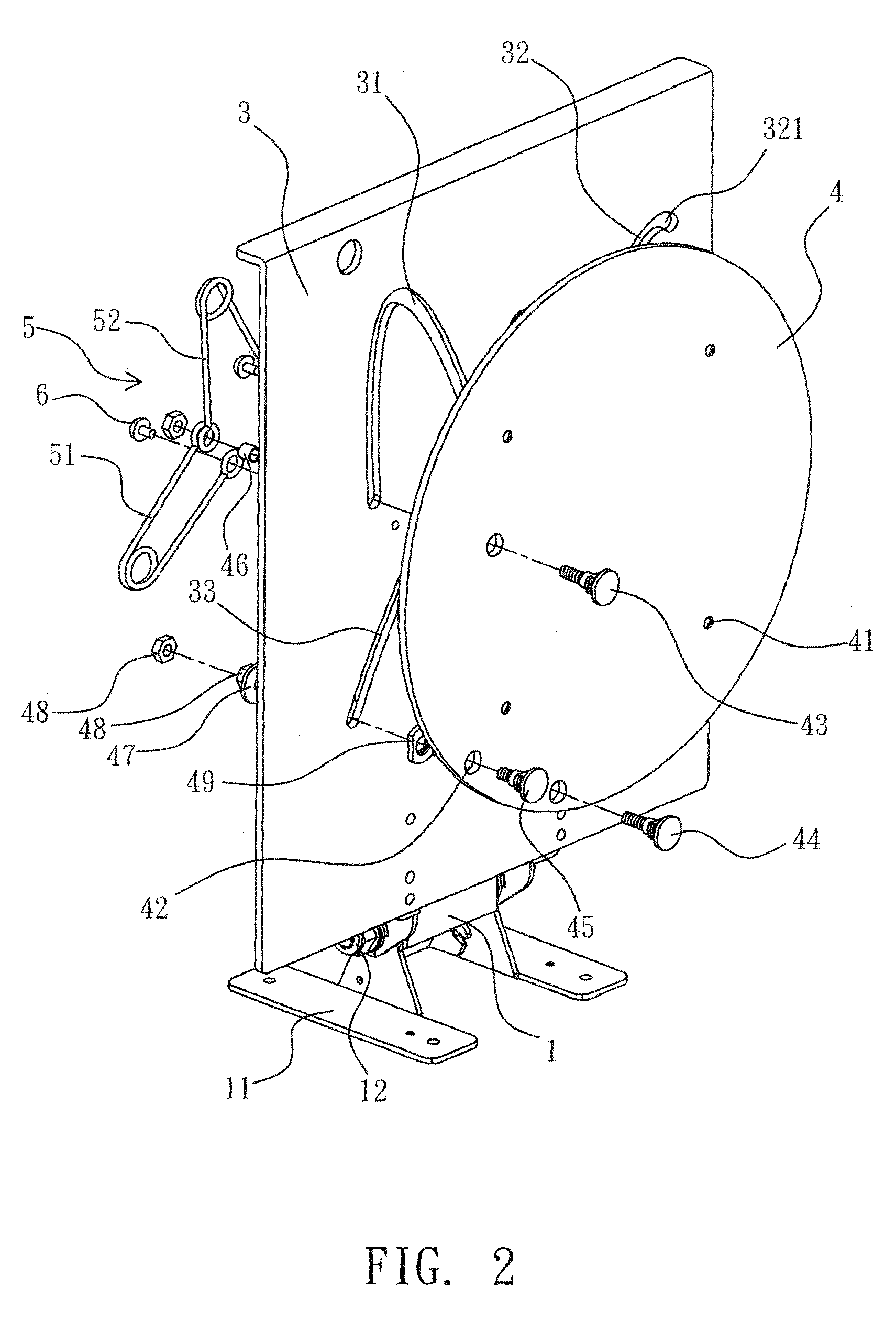
[0017]As shown from FIG. 1 to FIG. 3, the supporting structure provided by the present invention is composed by a base seat 1, a supporting rack 2, a retaining member 3 and a rotating member 4.

[0018]The base seat 1 is a seat member having at least one seat stand 11 for being placed on a surface of a desk. The top end of the base seat 1 is connected to the supporting rack 2 via a hinge 12, so the tilting angle of the supporting rack 2 can be adjusted with respect to the base seat 1.

[0019]The supporting rack 2 is provided on the base seat 1, the supporting rack 2 is pivotally connected to the base seat 1 via the hinge 12, or the supporting rack 2 can be directly connected to the base seat 1. The front end of the supporting rack 2 is provided with at least one supporting arm 21 for being connected to the retaining member 3, so the retaining member 3 is retained at the front end of the supporting rack 2.

[0020]The retaining member 3 is a sheet member disposed on the supporting arm 21 pro...


PUM


Abstract

The present invention relates to a planar rotation mechanism of supporting device, includes a base seat; a supporting rack; a retaining member and a position located at a top portion of a lateral side of the retaining member, a diagonal position of the retaining member and a position between the above two positions are respectively provided with a first, a second and a third guiding slots with different curvatures and lengths; and a rotating member respectively provided with a column hole with respect to the initial positions of the first, the second and the third guiding slots for allowing a first, a second and a third guiding columns respectively pass through the corresponding column holes and the corresponding guiding slots, so the guiding columns can respectively slide within the corresponding guiding slots; so when the rotating member is operated with a planar rotation with an object to be supported provided in front of the rotating member, the plural guiding columns slide within the corresponding guiding slots, a corner of one lateral side of the object to be supported is firstly moved a small distance alongside the bottom end of the object to be supported, then is rotated, so a horizontal status of the object to be supported is switched to a vertical status or vice versa.

Description

BACKGROUND OF THE INVENTION[0001]1. Field of the Invention[0002]The present invention relates to a planar rotation mechanism, more particularly to a planar rotation mechanism of supporting device that can be used in situations that when an object to be supported, e.g. a flat panel monitor, is operated with a planar rotation (switch from horizontal to vertical or vice versa), one corner of the lateral end of the object to be supported is firstly and horizontally moved a small distance alongside the bottom end of the object to be supported then is rotated.[0003]2. Description of Related Art[0004]A flat panel monitor, such as a LCD monitor, a LCD TV or a plasma TV, has advantages of light in weight, thin in thickness and no radiation. Therefore, most of CRT TVs are replaced. In order to let a flat panel monitor being uprightly disposed, a connecting unit is served to connect the flat panel monitor to a base seat, and a hinge is provided between the flat panel monitor and the connecting...

Claims


Application Information

Patent Timeline
IPC IPC(8): F16M11/10
CPCF16M11/10F16M11/105F16M2200/041F16M11/2021F16M11/18
Inventor LEE, YUNG-TAHSU, YU-TSUN
Owner JARLLYTEC CO LTD
Why Eureka
Try Eureka