Supercharge Your Innovation With Domain-Expert AI Agents!

Sheet conveying apparatus and image forming apparatus

a technology of conveying apparatus and sheet, which is applied in the direction of transportation and packaging, thin material processing, and article separation, etc., can solve the problems of catching the front end of the sheet and crushing the front end, bending or ripping, and adverse possibility

Inactive Publication Date: 2009-10-01
CANON KK
View PDF1 Cites 7 Cited by
  • Summary
  • Abstract
  • Description
  • Claims
  • Application Information

AI Technical Summary

Benefits of technology

The present invention is about a sheet conveying apparatus and an image forming apparatus that can prevent the front end of a sheet from getting bent, folded, or ripped on the outer edge of a roller. The apparatus includes a guide member that is supported on one of the rotating bodies and can move outward to prevent the sheet from hitting the roller. When the sheet pushes the guide member, it retracts back into the space between the rotating bodies to allow the sheet to pass through. This invention helps to improve the quality of sheets that are conveyed and processed by the apparatus.

Problems solved by technology

According to the pair of conveying rollers using the blast roller 80 having high surface friction coefficient, if a sheet having a curled front end is conveyed and abuts against the blast roller 80, there is an adverse possibility that the front end of the sheet is caught and the front end is crushed, bent or ripped.
Thus, locations having different conveying forces are generated in the axial direction of the pair of conveying rollers, and there is an adverse possibility that the sheet is fed on the skew or creased.

Method used


Image

  • Sheet conveying apparatus and image forming apparatus
  • Sheet conveying apparatus and image forming apparatus
  • Sheet conveying apparatus and image forming apparatus

Examples


first embodiment

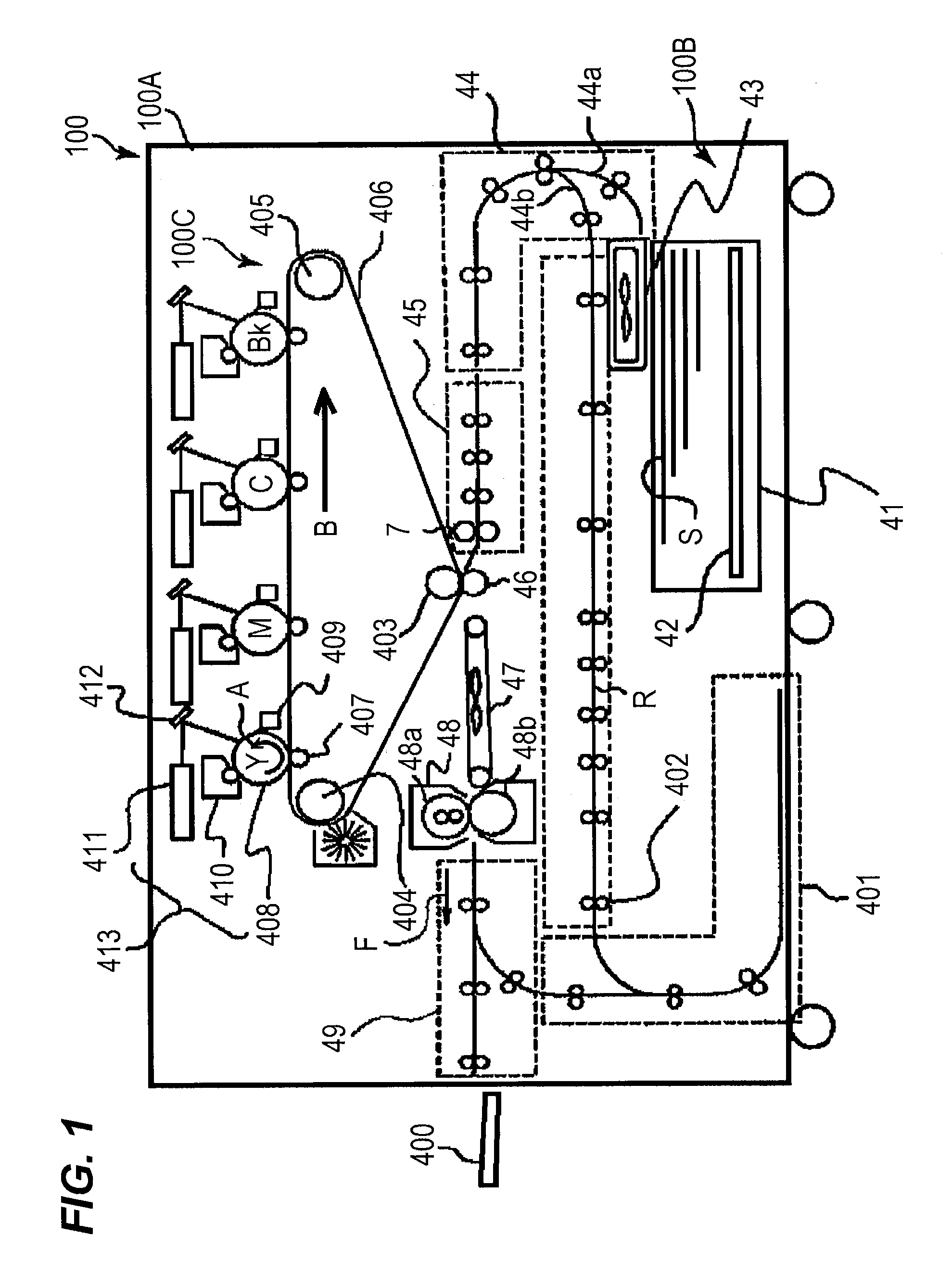
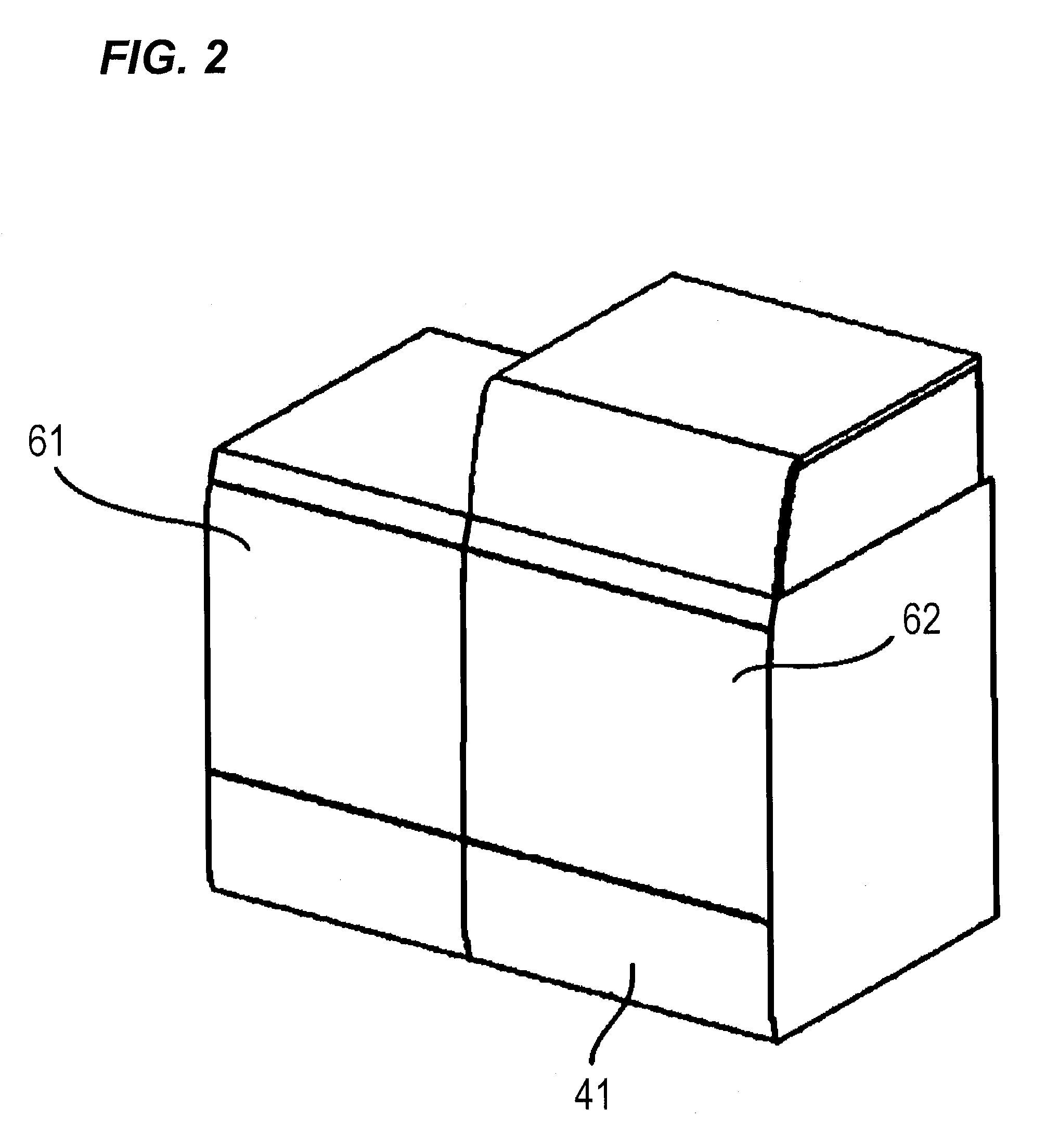
[0028]FIG. 1 illustrates a brief structure of a color image forming apparatus which is one example of an image forming apparatus having a sheet conveying apparatus according to a first embodiment of the present invention. FIG. 2 is a perspective view of the image forming apparatus.

[0029]FIG. 1 illustrates a color image forming apparatus 100 and a color image forming apparatus body 100A (apparatus body, hereinafter). In FIG. 2, a front surface of the apparatus body 100A of the image forming apparatus 100 is covered with double door type front covers 61 and 62. A sheet storage portion 41 is disposed at a lower portion of the apparatus body 100A, and the sheet storage portion 41 can be pulled out in the front surface direction. The color image forming apparatus can be classified, based on structures, into a tandem type in which a plurality of image forming portions are arranged side by side, and a rotary type in which the plurality of image forming portions are disposed cylindrically. ...

second embodiment

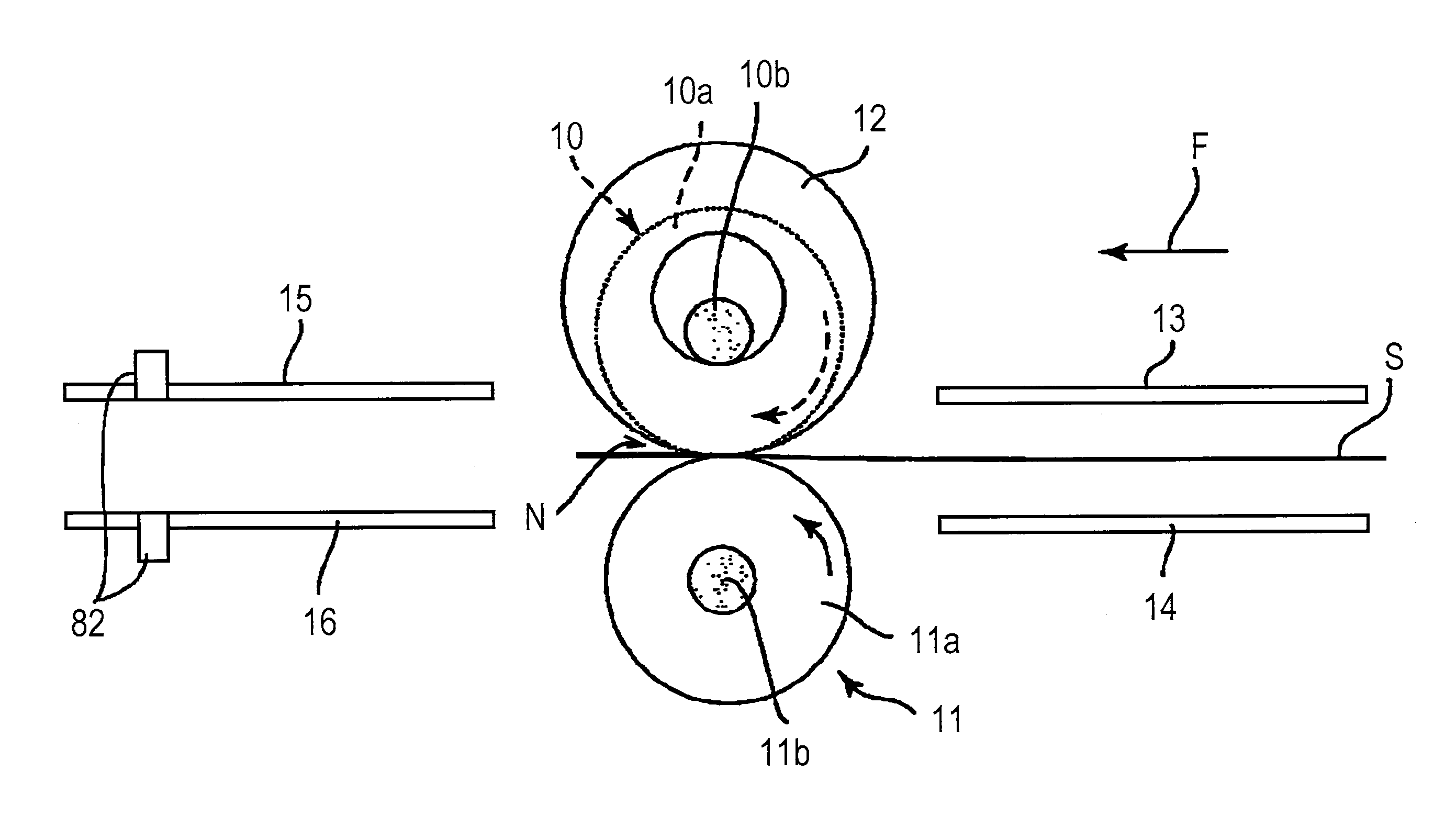
[0066]In the first embodiment, the upper conveying roller is provided with the guide member to prevent a front end of a sheet from curling upward. The second embodiment will be described based on a case where the lower conveying roller is provided with the guide member to prevent a front end of a sheet from curling downward. The same structures as those of the first embodiment will be designated with the same symbols, and description thereof will be omitted.

[0067]FIG. 9 is an explanatory diagram illustrating an essential portion of a sheet conveying apparatus of the second embodiment.

[0068]In the second embodiment, a guide member 12 is formed into a disk-like shape having a diameter larger than a rotating body 11a, the guide member 12 is loosely fitted to a shaft 11b which supports the rotating body 11a and is rockably supported. That is, a hole 12a having a diameter larger than that of the shaft 11b is formed in the center of the guide member 12, and a shaft 11b is inserted into th...


PUM


Abstract

A sheet conveying apparatus includes a guide member disposed in a space on a side of a pair of rotating bodies. The guide member is supported such that the guide member can project outward from an outer periphery of one of the rotating bodies located upstream in a sheet conveying direction. When a front end of a conveyed sheet abuts against the guide member and pushes the guide member, the guide member retracts from a projecting position into the space on the side of the pair of rotating bodies, and in this state, the front end of the sheet is guided to a nip portion of the pair of rotating bodies.

Description

BACKGROUND OF THE INVENTION[0001]1. Field of the Invention[0002]The present invention relates to a sheet conveying apparatus which nips a sheet by a pair of conveying rollers and conveys the sheet, and to an image forming apparatus having the sheet conveying apparatus.[0003]2. Description of the Related Art[0004]A conventional image forming apparatus such as a copying machine, a printer and a multifunction machine includes a sheet conveying apparatus which nips a sheet using a pair of conveying rollers and conveys the sheet as a system which conveys a sheet. An electrophotographic system is widely used in the image forming apparatuses, the image forming apparatus of the electrophotographic system conveys a sheet after toner is transferred to the sheet to a fixing portion, applies heat and pressure to the sheet, and the toner image transferred to the sheet is fixed. Since heat and pressure is applied to a sheet which passed through the fixing portion, a shrinkage difference is genera...

Claims


Application Information

Patent Timeline
Patent Type & Authority Applications(United States)
IPC IPC(8): B65H5/06
CPCB65H5/062B65H2407/30B65H2404/11B65H5/36
Inventor ISHIOKA, NAOKI
Owner CANON KK
Features
  • R&D
  • Intellectual Property
  • Life Sciences
  • Materials
  • Tech Scout
  • Unparalleled Data Quality
  • Higher Quality Content
  • 60% Fewer Hallucinations
Learn More